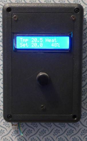
AVR Thermostat
Ver. 2
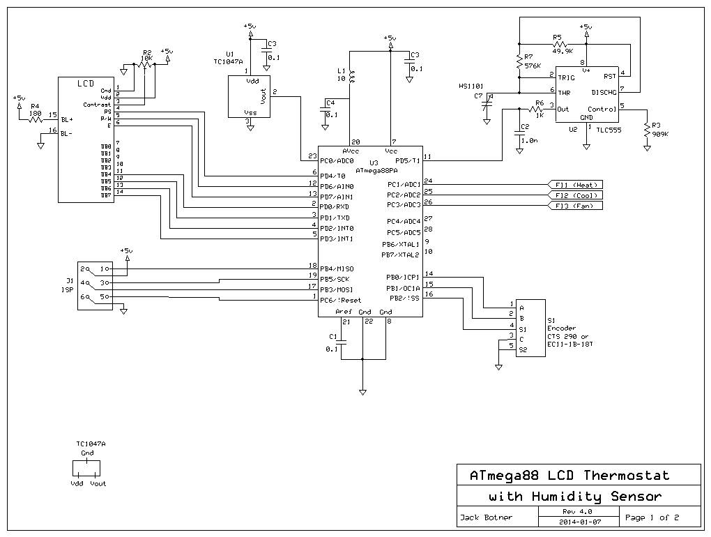
This thermostat is built around an ATMega88PA and a TC1047A temperature sensor. It controls your furnace and air conditioner. It is not programmable. The unique features are a humidity sensor and the use of a pushbutton rotary encoder instead of a bunch of pushbuttons and switches. This is a rebuild of my previous thermostat that had a real time clock. I decided that a humidity display would be more usefiul than the time. As an aside, I never found a programmable thermostat very useful. Usually I just turn it up in the morning and down at night, and if I'm going to be out for a while.
The ATmega88PA has plenty of I/O and memory. The LCD is the usual 16x2 parallel I/O. The TC1047A temperature sensor is easy to program to, if you don't mind its tiny size. The humidity sensor is a HS1101, the same as in my temperature/humidity meter project. Parallax (p/n 27920), Digikey (27920-ND). Finally there's the rotary encoder; I used a CTS 290 pushbutton encoder. (See my rotary encoder page.) The encoder outputs a 2 bit code which allows you to tell if it is being turned clockwise or counter-clockwise. In addition it has a pushbutton built-in to the shaft.
The most interesting part of this project is the use of the rotary encoder. In run mode, turning the knob raises or lowers the temperature setting. Press the button and you enter the options menu. The first menu lets you select heat, cool, or off. The next menu lets you turn the fan on or off. After a few more menus you can tweak the ATmega88's OSCCAL register if you like, then the unit returns to the run mode again.
This thermostat is powered by the furnace. There are no batteries to replace. The last set temperature and mode is remembered in EEPROM so it always returns to the previous state after a power off. What I really like is keeping the LCD backlight on all the time, since there is no need to conserve battery power.
To make this possible you need access to the "C" wire in the furnace, which is not normally run to the thermostat. My thermostat had "RH" and "RC" wires which were both connected to the "R" terminal in the furnace. RH and RC connect to the same place in the furnace, so only one wire is needed. All I had to do was move one wire to the "C" terminal (the unused one!).
You may find the terminology of the thermostat/furnace connections confusing, I certainly did. I am not in the heating/AC business so my knowledge is based on study of the (crude) furnace schematic and my own speculation. The furnace contains a 24V transformer which powers the control system. One lead of the 24V secondary is common/ground and called "C". The hot side of the transformer secondary is called "R". "R" is delivered to the thermostat which contains one to three switches to activate the functions of the furnace and A/C. Each switch requires one wire back to the furnace controller. The one switch all thermostats have is heat, which is returned to the "W" terminal in the furnace. If you have A/C, the cool switch returns to the "Y" terminal. Finally if you have a Fan On switch, it is returned to the "G" terminal.
There may be other kinds of furnace control systems in use. Please make sure your furnace corresponds to my description before you try anything. You could damage your furnace controller. I cannot be responsible.
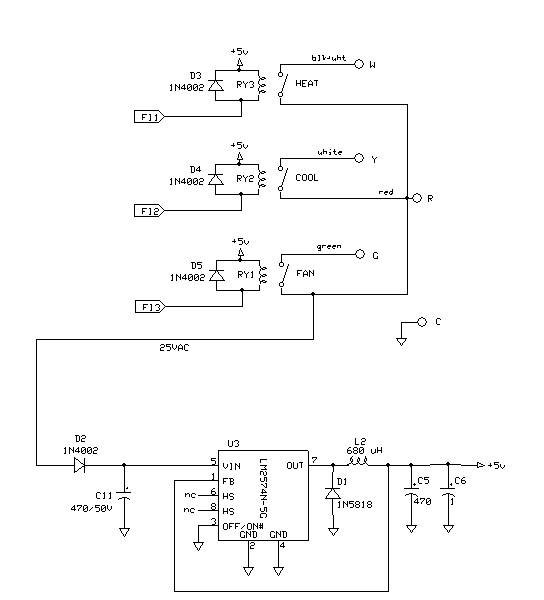
In order to get power from the furnace I accessed the 24 VAC across the "C" and "R" terminals, rectified by D2, filtered by C11 and regulated by U3. My switches are relays, RY1 RY2 and RY3. I happened to have a few SPST reed relays that operate at 5V and 10 mA, so they can be driven direcly from the AVR I/O port. These relays are labelled "Hamlin HE321A0400 8006". I rescued them from an old PCB many years ago. (The Fan On relay has been energized in my previous project for years now and still works!)
J1 (in-circuit programming connector) was used during development but you can leave it out if you like.
Thanks to Peter Fleury for the
AVR LCD routines, which I've used in many of my AVR LCD projects.
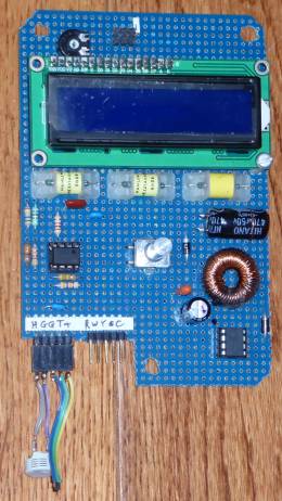
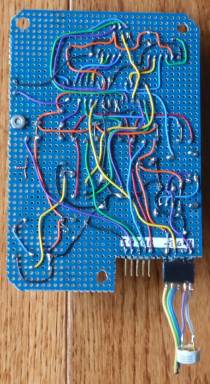
On the left photo, the ATmega88 is mounted directly under the LCD. You can see the temperature and humidity sensors plugged into the left header; the right header contains the connections to the furnace. They go via ribbon cable to the back of the case where I glued in a screw type terminal block for the furnace wires.
I use a LM2574N switching regulator, since the input voltage was pretty high (around 35V) and the current around 150 MA. The LM2574 barely gets warm. The only trick is using the correct inductor for L2. I am not a big fan of toroid cores, since I have a box full of them and don't know what most of them are. Still I decided to wind my own inductor. First I tried one core that required around 40 turns to give 1 mH. When I tried the circuit, the LM2574 got hot as blazes! So I tried another core, rescued from an old PC switching supply, and found it needed 300 turns for 1 mH. This time the circuit worked perfectly, with very little heat. I used #24 wire, although #26 should be OK too. I think that the 1st core was a ferrite, and saturated at too low a current, dropping the inductance drastically, overworking the poor LM2574. The 2nd core must be powdered iron, just what was needed. A good clue is that ferrite cores require a lot less turns than iron, although the mix and frequency would have some effect on that, etc. etc. My old ARRL Data Book has some information on toroid cores, but not what I should do with my box of unknowns. The ON Semiconductor spec sheet has some very useful information on selecting the inductor and other components. Magnetics has a lot of information on toroids. Another helpful reference on toroids can be found here. And here's a neat toroid calculator program. Update: If I were building this now, I would use a Recom Power DC-DC Converter p/n R-78E5.0-0.5, Digikey 945-1648-5-ND.
The temperatures are shown in degrees C. A minor code change would be required to show temperature in degrees F. The code is compatible with WinAVR, so anyone can make changes.
Regarding the ATmega88AP fuses, the internal clock is used. The watch dog timer is enabled, as is the brown-out detect, at the 4.3V setting.
Download C source code for AVR Thermostat