Temperature and Humidity Meter
This project is a combined temperature and humidity meter. It is an improvement on my PIC-based humidity meter and my PIC and AVR thermometers. I use an ATmega164, which as lots of I/O and memory.
Update: An HDC1080 I2C sensor version of this project can be found here, and a SHT30 version here.
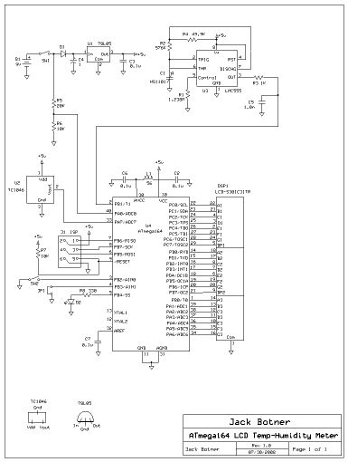
The humidity sensor is a HS1101, made by Parallax (p/n
27920) and available from Digikey (27920-ND) for around US$10. The
circuit for the humidity meter sensor is identical to
the earlier project. I had made a mistake in construction, which
resulted in erratic operation. The problem is that the HS1101 must be
physically as close to the LMC555 as possible. I had run a 4-inch
wire to the circuit board, and the unit became sensitive to noise
picked up from the surroundings. In this version, I placed the sensor
board at the top of the case, where the HS1101 can plug right in to the
circuit.
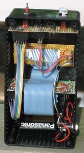
At the top of the unit you can see the TC1046 temperature sensor
(Digikey TC1046VNBTRCT-ND) and the HS1101 humidity sensor. The board at the top contains the
LMC555 circuit and the power supply regulator. A 6 conductor cable goes
the the lower board, which contains the CPU. The middle board has the
LCD display and 2 switches. The switches hold the board in place. There
is a 26 conductor ribbon cable to the CPU board just below. Since the
LCD uses little power, the unit is battery operated (with provision for
an external power supply), another big improvement over the older
projects. The battery and holder are at the bottom of the case. The
power leads go to the on/off switch (SW1) and then to the sensor board
regulator, and regulated power goes to the CPU board.
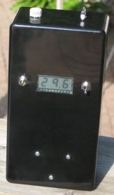
The LCD display is a Lumex LCD-S301C31TR 3 digit unit (DigiKey 67-1788-ND) with
no controller or backlight. I must
admit that this LCD display is a pain to use. You need 24 connections
to the CPU (hence the large ribbon cable in the photo), and the program
must drive each segment to make up the
display. However it is cheap (~C$3.50), and as
mentioned, uses little power. I just wish there was provision for a
backlight. I also want to note that this display is a static LCD, and
normally requires an AC signal to drive the segments. A very good
write-up on the subject can be found here.
However I did not implement this, as I find that the Lumex display
maintains its contrast for some time after power-up. I never leave the
unit on for more than a few seconds at a time, so this is not a problem
for me.
When you switch the unit on, the battery voltage is
sampled via R5 and R6 and ADC0. For 2 or 3 seconds, the battery voltage
is displayed. Then the display changes to temperature or humidity,
depending on the setting of SW2. Other improvements are the choice of
Celsius or Fahrenheit (JP1), and the ability to display negative
temperatures. The temperature sensor is connected to ADC7 and uses the
internal 1.1V Vref. A digital median filter is used to smooth out the
temperature display. The humidity circuit generates a squarewave which
is connected to T1. Timer0 is programmed to give 1 second intervals,
where the T1 count is read and reset. An interpolating routine is used
to get humidity from the measured frequency.
Download C
source code for the project
Back
to VE3LNY's AVR Project Page
