The requirement
You need some sort of simple to built and inexpensive gadget to match your HF transceiver to a wide range of antenna impedance load conditions. (In fact almost any old piece of wire you might care to hang up). You would also like it to match both unbalanced and balanced loads on all HF bands.
Ask somebody what to do and you will probably get the answer: The Z Match.
Considering all the data we have published on Z match tuners and the different circuit arrangements we have investigated, one could be forgiven for being confused about which Z Match design one should choose to satisfy the criteria of the opening paragraph. Based on all the experimental work I have carried out, here is what I select as a simple design which has been fine tuned to match a wide range of antenna impedance conditions:
The Design
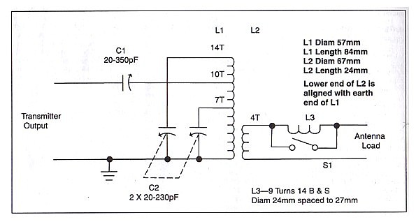
The circuit diagram is shown in figure 1. The circuit arrangement of L1-L2, C1 & C2 is identical to that which I described as the AR Single coil Z Match, Amateur Radio (AR) April and May 1993.
 |
Coils L1 (57 mm diam.) and L2 (67 mm diam.) are wound with
around 16SWG gauge enamel wire. The precise gauge is not critical
but the heavier the gauge the better the efficiency one might
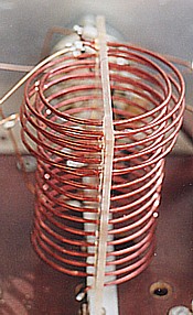
expect from the tuner. The former (figure 2) is made from perspex*
sheet and drilled as shown to support the individual turns of the
coils. The inner holes support L1 and the outer holes L2. Initially
wind coil Ll close spaced on a round former which has a diameter
less than 57mm and with a few more turns than the 14 specified.
Release the winding from the round former and allow the winding to
expand to the right diameter . (Some experimentation may be
required to get the initial diameter right in the first place).
Thread the winding by rotation into the support holes in the
perspex former. Trim off the winding at 14 turns and clean off the
enamel insulation for soldering connections at the ends. Also clean
off enamel for soldering tap points at 7 and 10 turns. |

The same treatment is repeated for L2 by first winding on a round former (in this case something less than a diameter of 67 mm) and then threading the coil into the outer holes.
Variable capacitors Cl and C2 are tuning gang types with around 0.25 mm plate spacing and recovered from old radio receivers. Whilst these capacitors might be difficult to purchase off the shelf, they are often picked up at amateur radio trading marts. The plate spacing is fine for the usual transceiver RF power of 100 watts. It is a bit marginal for higher powers and under some matching conditions, arcing across the plates might be experienced at the amateur power limit of 400 watts.
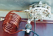
The coil assembly can be mounted using a small L bracket fitted to the perspex sheet at one end of L1. Heavy connecting bus bars between L1 and the tuning capacitors can provide support to the other end of the coil assembly. In the sample shown in the photograph, a base plate was made from a sheet of insulating material and an L bracket fixed the "hot" end of L1 to this. The other end (or earthy end) of the coil assembly was mounted upward and bus bars connected to this end steadied the assembly.
If you refer to the original Single Coil Z Match articles, you will see that L3 and S1 are not included and they are a further addition. In fact for most matching conditions, they will not be needed and L3 will be switched out by SI. However a characteristic of the L Match network, formed by the Z Match Tuner circuit, is that to match low resistance loads, some reactance is required to be reflected back to that network. In the Z Match circuit, this is provided from either reactance reflected from the antenna load, or by reactive characteristics of the L1/L2 coupling circuit, or by a combination of both. The antenna load impedance might be capacitive reflecting a capacitive reactance. If by chance this reflected reactance happens to be close in value to the inductive reactance caused by the characteristics of L1/L2, then the two reactances cancel or near cancel. For this condition, a match is unlikely to be achieved for an antenna resistance component somewhat lower than around 80 ohms. This explanation is bit simplistic but the theory of this phenomena was explained in more precise detail in our article - Amateur Radio, March 1997 (Butler & Thornton).
| To get over the problem when this occurs, some extra reactance is simply switched in by the addition of L3. In practice, if a match cannot be found by adjustment of Cl and C2, then switch in L3 and try again. |
The inductance of L3 is not critical. As specified in figure 1, it has an inductance of close to 1.2 uH. Air wound with a heavy gauge wire, it can be made self supporting by soldering its ends to insulated mounting tags. Apart from its use in the particular single coil tuner described, the inclusion of the circuit (L3-SI) is a very useful addition to any Z match tuner design to cope with the sort of condition I have discussed.
Except for some sort of front-panel/base assembly or container box (left to one's own imagination), the only other major components are two vernier dial drives fitted to the two tuning gangs. The capacitor settings for a match in a Z Match Tuner are usually quite critical and the vernier drives are quite essential to carefully locate these settings and hold the capacitors locked. I find its best to tune with both hands, one on each dial, as it is sometimes necessary to chase one dial setting after the other leading into the optimum settings.
In Conclusion
Follow the design as described (particularly the precise specification for Ll-L2 coil assembly) and you will have a unit to a design which has been "fine tuned'' so that it will match most of the impedance loads you might encounter.
It can be used on all the amateur bands of 3.5 to 28 MHz with either a balanced or unbalanced load.
Power efficiency is very good for frequencies up to 14 MHz and for load resistances up to 200 ohms (This was discussed in AR Sept. 1995). Some loss in efficiency can be expected as load resistance is raised higher.
Output balance is quite good for frequencies up to 14 MHz and balanced load resistances up to 1000 ohms. (This was discussed in AR April 1996).
A Few notes on its Operation
The Z Match is really a basic L Match of variable series C and variable shunt L coupled via an RF transformer. The variable shunt L is achieved by using a fixed shunt coil in parallel with a variable capacitor. The variable shunt capacitive reactance in parallel with the fixed shunt inductive reactance provides the means to vary the resultant shunt inductive reactance. This is the advantage of the Z Match - there is no need for either a tapped and switched inductor or roller inductor, both of which have disadvantages. The tapped inductor cannot always be set exactly to the desired matching inductance. The roller inductor apart from being bulky often has to be rotated many times to set for band change.
In its basic form of single capacitor and single inductor, the L match is an unbalanced network not suitable for balanced lines. By providing a separate output coupling coil L2, the Z Match allows coupling to balanced lines.
To understand the operation of the Z Match, you must first understand the concept of the L match as a tuned circuit and the relationship between the resistance loaded across a tuned circuit and the resistance seen in series with it for a given value of loaded Q. To brush up on this, I suggest reading the first few pages of the Graham Thornton article on the L Match (See reference below).
Another feature of the Single Coil split stator C2 and tapped L1 arrangement is that it can parallel resonate at two different frequencies for the one setting of C2. Hence, the circuit can match two different tuning ranges and achieve a wider tuning range than for similar values of components in a simple LC parallel connection. This has been explained by Tom Seed ZL3QQ in March 1992 issue of Break-In.
The whole concept of the Single Coil Z Match is quite simple in principle and the unit is simple to construct. I have experimented with the single coil arrangement to finalise on this particular circuit arrangement as shown. I have been able to confirm by extensive testing that it will match a wide range of load conditions on all the Amateur HF bands. Twin coil designs have been around for a long time but this single coil unit can do it all.
Further articles on the Single Coil Z Match
Modifications for 1.8 MHz - Click Here
A QRP Z Match using a Toroidal Cored Coil - Click Here
A Z Match made for Higher RF Power - Click Here
Tuning v/s Load Curves - Click Here
Further background information on the Design and Characteristics of the Single Coil Z Match can be found in articles published in the journal "AMATEUR RADIO" as listed following: