 |
Introduction
In past issues of Amateur Radio I have tabled a lot of measurement data on the performance of Z match tuners including the range of load resistance that can be matched. However, in retrospect, measurement of power efficiency has been limited to loads of 50 ohms and efficiency over the whole load resistance range tested has not really been assessed.
The question of carrying out a wider range of efficiency tests came up when I received a small QRP (low power) version of the single coil Z match for examination. This unit was made with a coil of similar inductance to the original AR single coil Z match but this was achieved with a much smaller diameter coil with more turns. By setting the taps on the coil in the same proportion to the original AR unit, it produced the same performance in terms of load resistance range. However, the constructor of the unit was a little concerned that, in reducing the coil size, he might have degraded the efficiency too much. So, I set about measuring efficiency over the resistance load range of 10 to 2000 ohms. While I was on the job, I thought it would be of value to do this for other designs which have been well documented. As a result, I have produced curves for the efficiency of four of these designs at frequencies of 3.5, 7 and 14 MHz. I also looked at the AR single coil unit padded up with capacity for 1.8 MHz.
It has been said that we have already had enough published on the design of the Z match but I felt that the curves demonstrated some important characteristics which should be documented.
Method of Measurement
The curves were formed by taking efficiency measurements at a number of different values of load resistance over the load resistance range and interpolating between measured values.
To start the test, the Z match is fed from a noise bridge connected to a receiver tuned to the required frequency. The noise bridge is set to 50 ohms and zero reactance. The selected load resistance (RL) is connected to the output of the Z match which is then adjusted for a match indicated by a signal null in the receiver. The impedance presented by the input of the Z match is now a resistance of 50 ohms.
The bridge input is replaced by a signal from the 50 ohm output of a signal generator tuned to the same frequency as the receiver. Using a high impedance probe, a reference voltage (Vi) is recorded across the 50 ohm input of the Z match and an output voltage (Vo) is measured across the load. Power efficiency is then calculated from the square of the ratio Vo/Vi multiplied by 50/Rl.
Voltage ratio between Vo and Vi is all that is required, rather than exact voltages, and I used the scale calibration of my CRO in conjunction with high impedance divide by 10 probes. Such probes have a shunt capacitance of 10 pF which can considerably modify the effective load impedance, particularly at the high values of load resistance at the higher frequencies. It is important when adjusting the Z match for the matching null that the probe be left across the load. The Z match adjustment then includes correction for the capacitive reactance caused by the probe.
Efficiency tests were carried out at 3.5, 7 and 14 MHz for loads ranging from 10 to 2000 ohms. I did not attempt measurements above 14 MHz as the test set-up was getting a little "touchy" at 14 MHz and I did not think 1 could rely on the validity of the results at any higher frequency.
The Models Tested
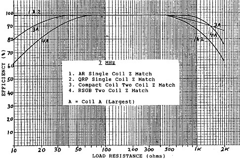
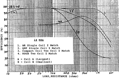
The curves (Figures 1, 2 & 3) have been taken on the following Z match models:
(1) AR Single Coil Z match as described in Random Radiators, Amateur Radio, August 1992 and in my report in Amateur Radio, April and May 1993.
(2) The QRP Single Coil Z match, similar in circuit design to the AR unit but which has a smaller coil construction as follows;
Primary 25 turns, 26 mm diameter, length 64 mm
Primary Taps - 13 and 17 turns
Secondary 6 turns, 32 mm diameter, length 13 mm
(3) The Compact Coil or Rononymous Two Coil Z Match as described in Random Radiators, Amateur Radio, March 1990 and in my report in Amateur Radio, December 1990.
(4) The earlier Two Coil Z match as described in the RSGB Handbook and based on an early design by Alien King W1CJL.
The samples of the AR single coil Z match and the Compact Coil two coil Z match were my own. The QRP single coil Z match was sent to me for testing and the RSGB type two coil unit was kindly loaned to me by Rob Gurr VK5RG.
The Results
Test results for 3.5, 7 and 14 MHz are shown by the curves of Figures 1, 2 & 3 respectively and these reveal some interesting characteristics. Let's first look at the two coil Z matches on 3.5 MHz. The original idea of the two coil unit was to use the larger coil (coil A) for 3.5 and 7 MHz and the smaller coil (coil B) for the higher frequencies. Experimenters soon found that, to make the Z match work over a range of load conditions, they sometimes had to deviate from that rule. In my experiments, I found that at 3.5 MHz it was necesary to switch to coil B of the RSGB circuit below loads of 200 ohms resistance and coil B of the Compact Coil unit below loads of 100 ohms resistance. Figure 1 shows that, whilst the values above these figures using coil A give quite high efficiency, the lower resistance loads using coil B give efficiencies in the order of only 60% to 70% - quite a discouraging result for the two coil unit.
|
All units have the tendency to fall off in efficiency as load resistance is increased above 200 to 300 ohms. For high resistance loads at 3.5 MHz, the two coil units show a better result than the single coil units. As might be expected with its lower value of unloaded Q, the smaller coil QRP single coil unit degraded in efficiency to the greatest extent, failing in value for loads beyond 100 ohms.
Referring now to Figure 2 for 7 MHz, all units do quite well. Over the load range of 30 to 1000 ohms, efficiency is at least 90%. Below 30 ohms the efficiency of the two coil units is reduced and above 500 ohms the single coil units fall away a little more than the two coil units.
 |
At 14 MHz (refer Figure 3), the smaller QRP single coil Z match gave the best result maintaining at least 90% efficiency over a load range of 10 to 1000 ohms. The RSGB unit using coil B produced high efficiency up to a load of 300 ohms above which I couldn't get a match and had to switch to coil A which gave a lower efficiency result. The AR single coil unit produced an efficiency of at least 90% for loads up to 250 ohms above which efficiency deteriorated considerably as the load resistance was increased. For some reason or other, the Compact Coil two coil unit really suffered in its result for loads above 150 ohms, failing to the greatest extent of all the units tested at this frequency.
 |
In my article in Amateur Radio April 1993, I showed how the AR Single Coil Z Match could be extended down in operation to 1.8 MHz and further in my article in Amateur Radio, October 1994, I included a circuit of my own constructed version which matched a load range of 10 to 100 ohms. Whilst I was on the job of measuring efficiencies, I also included this unit at 1.8 MHz and the result is shown in Figure 4. For the typical 1.8 MHz Marconi antenna arrangement (often less than 1/4 wave), we might expect antenna resistances in the order of 15 to 35 ohms. From the results (Figure 4), the anticipated tuner efficiency for these loads is in the order of 85% to 90%.
 |
Single Coil Z Match Tuner Efficiency at 1.8 MHz. |
Some Conclusions
The curves show that efficiency of the various Z match tuners varies considerably with variation in frequency and load resistance. The AR Single Coil Z match which we promoted in 1993 is shown to have high efficiency for load resistance between 10 and 200 ohms. On some frequencies, it becomes less efficient as the load resistance is increased above the 200 ohm point. For the general run of antenna systems, the resistance component reflected by the system is more likely to be less than 200 ohms and hence loss of efficiency for high resistance loads is not as great a concern as loss of efficiency at low resistance loads.
However, for the two coil Z match units, the need to use coil B below 100 to 200 ohms on 3.5 MHz gives a loss in the unit of about one third of the power (or about 1.8 dB). This represents a fraction of an S point and on the air could go unnoticed. However, it is a loss of power we would prefer to do without for the usual low resistance antenna load. The good news is that it can be fixed.
The two coil Z match units can be made to tune low resistance loads on coil A by simply tapping back the secondary turns of that coil. On my Compact Coil unit, I tapped back the secondary of coil A from the designed seven turns to four turns and found that I could still tune over the whole load range of 10 to 2000 ohms for both 3.5 and 7 MHz but using only coil A. Of course this was what coil A was supposed to do in the first place. Efficiency for low resistance loads was now restored to much higher values and comparable with those achieved using the Single Coil unit. I did not feel I should mess around with the RSGB design unit I had borrowed from Rob but I anticipate that the RSGB unit would produce similar results if its coil A secondary was tapped back.
If nothing else, my tests have highlighted a deficiency in the performance of the two coil units and shown how this can be rectified. Considering the original reason for commencing the tests, they should also provide some assurance to our QRP Single Coil constructor that his unit is reasonably efficient provided that high resistance loads at 3.5 MHz are avoided.
Why the Compact Coil Two Coil Z match showed so poorly above 200 ohms at 14 MHz is a job for another day.
References
1. AR Single Coil Z Match - Lloyd Butler VK5BR - Amateur Radio April & May 1993. - Also refer to Random Radiators, Amateur Radio February 1993.
2. Tests on the Compact Coil Z Match - Lloyd Butler - Amateur Radio December 1990 - Also refer to Random Radiators, Amateur Radio March 1990.
3. Radio Communications Handbook - RSGB - Section on HF Aerials including Z Match.
4. Feedback on the Design of the AR Single Coil Z Match Tuner - Lloyd Butler VK5BR - Amateur Radio October 1994.