| |
|
Introduction
A typical amateur radio antenna installation makes use of a simple dipole or other balanced form of antenna fed via a coaxial transmission line. Because the line is unbalanced, some form of unbalanced to balanced coupling is normally necessary between the coaxial line and the antenna. Without this coupling, a condition is set up where currents running in the inner and outer legs of the coax line are unbalanced and a common mode or longitudinal current component is developed along the length of the line, causing radiation from the line. Apart from distorting the radiation pattern inherent to the antenna proper, it encourages annoying induction into equipment and wiring within the radio shack as well as on receiving encouraging induction of vertically polarised near field noise.
A typical balancing interface is the choke balun which must have sufficient common mode rejection impedance to minimise the longitudinal current component. Whilst most radio amateurs possess an SWR meter which can be used in series with the coax line to check how well the antenna is matched to the 50 ohm line, it gives no indication that the currents running in the two legs of the line might be unbalanced. The SWR meter can show a perfect 1:1 SWR indicating that the antenna is loading the line with a resistance of 50 ohms. However with such a condition indicated there can still be a high longitudinal component flowing and radiation from the line.
Whether there is a serious unbalance of currents in the line legs can easily be checked by measuring the two currents. However it doesn't seem to be something which is routinely done in checking out the antenna system and verifying whether the coupling interface (such as the choke balun ) is adequate for the job.
To check out balance of line leg currents in such antennas as the EH, I have previously made use of thermo couple RF ammeters, one inserted in series with each leg. I experienced current difference as high as 2 to 1. Such RF meters were commonplace in transmitters of an earlier era but I don't see them any more as items in our local electronics shops. Whilst Old Timers like myself still have them, they are probably not too plentiful on the shelves of radio amateurs more recently introduced to amateur radio.
Instead It seemed to me that there was a need for a simple test unit to check out the line balance by connecting it in series with the coax line much like one would connect in the SWR meter to check out the line to antenna matching. So the Transmission Line Balance Test Meter is born.
|
The Balance Test Meter
|
|
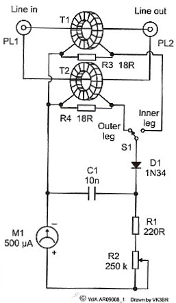
The 500 micro-amp meter used was selected from the spares box simply because it was a small one which fitted nicely in the housing box. With this meter, I get a comfortable reading using about 10 to 15 watts running in a 50 ohm line. However if the meter has to be purchased, I suggest aiming for a 50 or 100 micro-amp movement which would allow operation on considerably lower power.
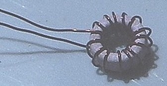
I used a plastic box which I purchased rather than one of the aluminium boxes I had on hand. I did this so that in fitting input and output connectors to the box, the outer poles floated. The connectors were mounted close together and their pole connections were each strapped together with the strap passing through one of the wound ferrite cores to form the primary of the current transformer. I used BNC connectors which by habit I have always used on my test gear. However the so called UHF connectors are quite standard on most commercially made amateur radio transceivers and one might prefer to fit the usual SO239 sockets.
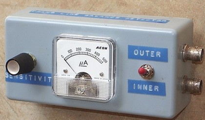
A photo of the finished unit heads the article. Figure 3 is a look at the rear. As can be seen I found a spare taddy strip to mount the few resistors and the capacitor..
 |
Check Out and Use of the Unit
To check out the test unit, feed the output of the transmitter set for low power through the unit into a 50 ohm dummy load using coax links. Set the transmitter output for low power. Make sure that the load is floating so that there is no return path from the dummy load via an earth connection. Adjust for a suitable reference reading on the meter adjusting the transmitter power, or the sensitivity control R1 on the unit, or both. The meter reading should read the same for both positions of the switch S1 and if so, the unit is ready to connect in series with the transmission line to check the line leg balance.
If when connected in series with the line, the meter reads near the same for both positions of the switch, the currents in the inner and outer legs of the line are near the same and one can be satisfied that there is little common mode current running in the line. If they are considerably different, then maybe an improvement in the antenna coupling interface is indicated.
I have talked essentially about currents in the inner and outer legs of a coax line. However as the connectors in the test unit are floating, the unit can also be used to check the comparative currents running in a line pair such as a balanced open wire feedline.
I wondered how much mismatch would be introduced in a 50 ohm line by the insertion of the coupling straps with the current transformers. So I fed the transmitter through an SWR meter and the test unit into a precision 50 ohm load. For 1.8 MHz and the HF amateur bands, there was no noticeable shift in the 1:1 SWR reading with the test unit connected except for a very slight shift at 28 MHz. I did observe that to get the same meter readings, a little more power was needed at the higher frequencies than at the lower frequencies. I didn't think this was important as the meter only had to make a comparison between two readings both at the same frequency.
I wasn't looking to use the unit at VHF but I did try it out on the 2 metre band. The meter gave readings OK but it did upset the SWR reading considerably. So to make a model of the unit for VHF, some improved form of current monitoring is indicated such as the method used on SWR meters made for VHF.
In conclusion I repeat what I said at the start. Checkout of whether there is common mode or longitudinal current component on the transmission line seems to be something which is rarely carried out. I have described a very simple instrument which can do the checkout by simply comparing the currents in the two transmission line legs. It is suitable for use on the HF bands and the 1.8 MHz band and can be used to check both coax lines and line pairs. If there is a longitudinal current component developed in the line, one can never be sure whether performance achieved is due to the antenna proper or due to radiation from the transmision line. Hence the need for this sort of test.
Relativity between the longitudinal and Differential Current Component
A further development of this meter provides direct reading of the relativity between the longitudinal current component and the differential component. (Click Here).