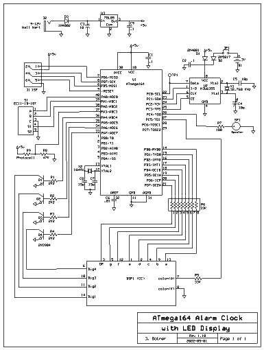
LED Alarm Clock
During the Covid-19 pandemic, I
had a lot of time on my hands so I decided to make another clock. This
one was to replace an old clock in my bedroom. I have several beefs
against many commercially made alarm clocks:
1. Too many buttons and switches, switches
become flaky after a while - when you press you get no response then it
skips digits
2. Buttons move time ahead only, going back
is hell
3. 9V battery backup - batteries are
expensive, don't last long, no warning when they fail
4. If power fails clock gains (never loses)
time
even with good backup battery
The best part was that I had all
the parts I needed on hand, including a nice 4 digit LED display,
although the display did have its challenges.

The LED display was the greatest challenge. It was
too bright.
I even tried using 47K resistors for the segments and it was stilll
bright. Some of the clock projects from ebay come with a film to
improve contrast, and I would recommend using it if available. My
solution was to use Timer2 to limit the time each display is
illuminated, and I was able to dim it down quite well. Once the display
is dim enough for nighttime use, it is too dim to see during the day, so
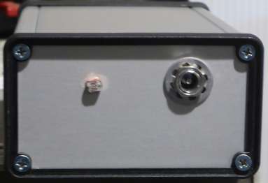
I added a photocell to increase the brightness during the day. You can
see the photocell on the back panel in the photo below.
The project uses a tiny speaker for the alarm. At first I
was
going to use a piezo buzzer, but it was too loud and there is no way to
tone it down. If you reduce the voltage with a resistor it just stops
buzzing at some point. And modulating the signal produced some wierd
sounds but not the desired result. The speaker is driven at 1 KHz from
Timer1, and the volume can be controlled by adjusting R7. I put a 500
ohm trimpot there and it works fine.
The photocell is a Photonics Detectors Inc. PDV-P9003,
Digikey P/N PDV-P9003-ND. It has a low resistance when illuminated,
around 1 to 2K, and a high resistance, > 100K in the dark.
Almost
any photocell should work here, you can adjust R8 and the trigger
threshold voltage in software if necessary. For my first try I
chose 47K for R8 and 2.5V
for the threshold, and it worked first time. Later I changed the
threshold voltage down to 1V to suit my environment. There is
a small
hysteresis in software to prevent flickering at the threshold point.
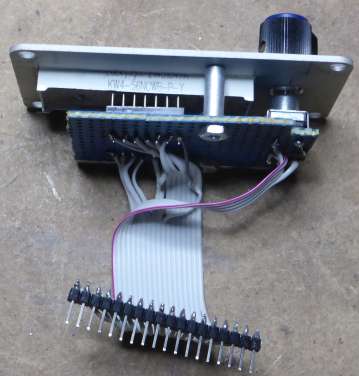
The pushbutton
rotary encoder is a model EC11-1B-18T
made by
Changzhou Xinze Electronic Co. It is very similar mechanically and
electrically to the CTS
series 290 rotary
encoder I used before. As a bonus it is easy to panel mount, (as long
as you can find a nut that fits it), and works quite well.
The
decimal point on the last digit indicates PM if on, and AM if
off. The decimal on the first digit indicates whether the
alarm
is on or off.
Programming
the clock is simple. Twisting
the encoder knob turns the alarm on and off. Going
from off to on, the alarm time is displayed for 2 seconds and there is
a short beep. Press
the
encoder button and programming mode is entered. First AL is displayed.
To program the alarm time press the button, then you can hours then
minutes. After pressing the button, the clock returns to normal
display, on the grounds that you will want to program the alarm most
often. To program the clock, turn the encoder knob when you see AL (if you
press the button you return to normal clock operation). Then CL
is displayed. Turn the knob to
return to clock display, press the button to program the clock time.
When programming time, first hours are shown, adjust with the knob,
press the button and minutes are shown, etc. Keep in mind that when
clock time programming is
complete and the button pressed, the time is updated in the NJU6355
with seconds set to zero.
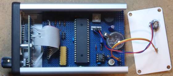
When power is off the NJU6355
is powered by its battery, a CR2032
coin cell. Alarm time and setting is stored in EEPROM so it will not be
lost. C4, a small 10pf ceramic trimmer capacitor, is used to adjust the
clock and it can be done quite accurately if you have a good frequency
counter. You must be able to modify main.c to add a call to rtc_test()
after initialization is complete. Run the updated program with the
frequency counter on TP1, and you should get a signal at 128 Hz. Adjust
C4 to get as close to 128.0000 Hz as you can. If your frequency counter
is accurate and has enough resolution, the clock should be spot on.
Then reload the original program.
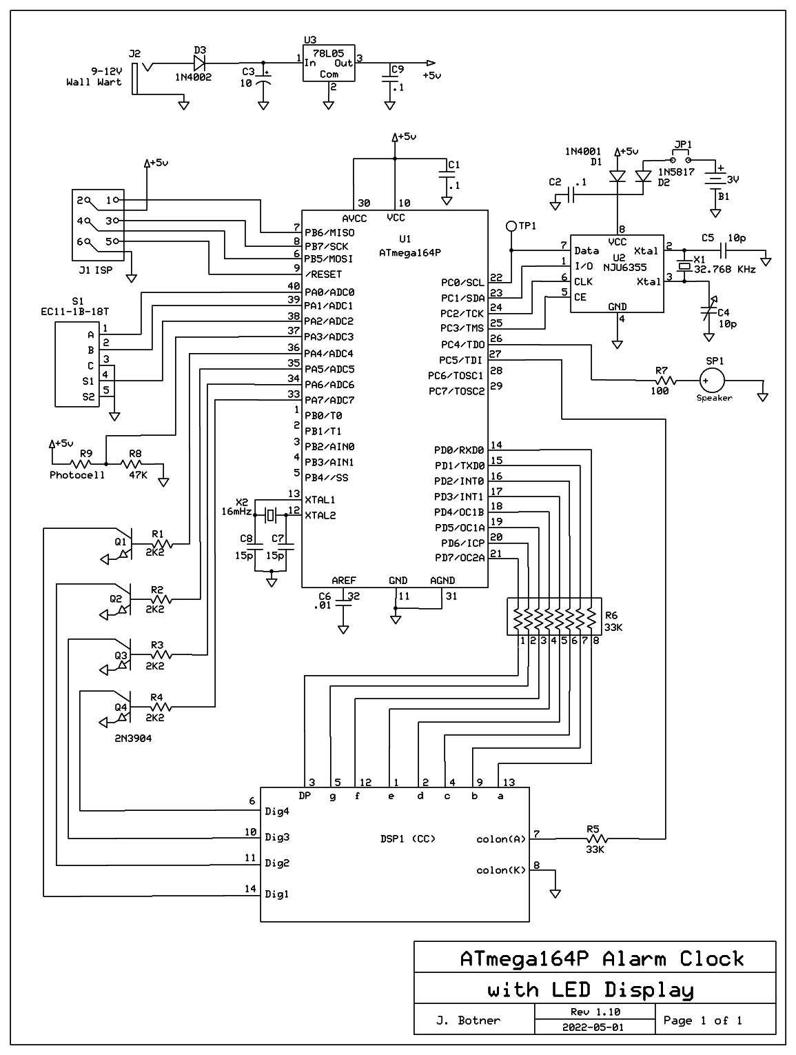
(The NJU6355 is no longer available. I used a DS1302 in this project, it could be used as a substitute here.)
The project requires a 5VDC external power supply. I used a USB
type charger wall wart, they all have plenty of current for this
project. I even found a USB cable with the barrel type power plug in my
collection.
One
more note on the display: I ended up using 33K resistors for R5 and R6. In spite of dimming
the display in software to 1/120 of the time for each digit, it was
still too bright for me. If your display is too bright or too dim, I
suggest playing with define LED_TIME_SLICES (in main.h) as well as the
value 4 assigned to ucLedTimeSliceLimit (in main.c when setting the
display to dim), and resistors R5 and R6. Note that LED_TIME_SLICES and the value assigned to ucLedTimeSliceLimit
must be a multiple of 4. The resistors determine the maximum overall
brightness of the display. Greater values of LED_TIME_SLICES
will allow for a dimmer display, but there is a practical limit which I
found to be 120. Assigning a value greater than 4 to ucLedTimeSliceLimit will also brighten up the display when dim, probably better to just reduce LED_TIME_SLICES.
Anyway I spent a lot of time fussing with my display, and I expect a
different display might require some fine tuning.
2022-05
Update: Added 78L05 regulator to power supply. Was getting nervous
about noisy output from cheap 5V switching power supplies. Of course
now you need a 9 or 12V wall wart. If you go any higher make sure the
78L05 doesn't get too hot, or replace it with a 7805.
Download C
source code for the alarm clock
Back
to VE3LNY's AVR Project Page