LED Travel Clock
Although I've built a lot of
clocks over the years, I
needed one more, one I could take with me on a trip. Since size and
weight were a factor, I decided to look for a commercially built clock.
I found a few candidates and even bought one, but the display was
unsuitable. Then I found a clock
kit that looked good, from a Chinese outfit called Banggood, for a
very attractive price, which I bought. (Update: there are newer, less expensive models with more features available on ebay.) In case the link doesn't work
anymore, the clock (in its optional clear plastic case) looks like this:
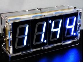
The
clock has a large bright (too bright for night use) LED display. It is
easy to build and looks great. It has a STC15F204EA microprocessor and
a DS1302 RTC, and two tiny pushbuttons on the side, which cannot be
reached when the clock is inside the optional case! Power is supplied
by a small 5V wall wart. Here is the spec
sheet. All the clock programming is done by these
two buttons, which is where the difficulties arise. Try as I might, I
could not consistantly program the clock. After wasting an hour, and because of the unreachable buttons, I
decided to build my own clock after all. But that display was so nice,
how could I make use of it? The problem was, the displays are soldered
on the bottom side of the PCB, so you lose access to the circuit board.
No way I could unsolder them either. I decided to take the following
approach:
- Throw out the optional plastic case
- Place the unit inside a larger case
- Build a daughter board with an ATmega88
- Using a 20 pin male header, connect the daughter
board to the relevant pins of the STC socket
- Include a rotary encoder, and ignore their
pushbuttons
- Replace
the 8 330 ohm LED current limiting resistors with 6.8K resistors*, to dim
the display. These could be unsoldered and removed from the top of the
circuit board thanks to the plated-through holes.
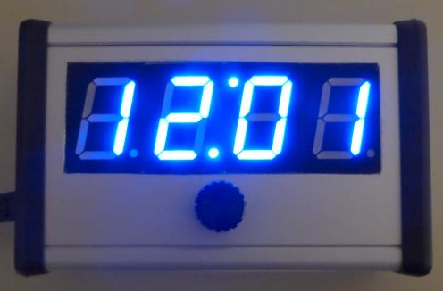
I
found a very nice aluminum project box in my collection, cut a large
hole for the LED display, and glued the original unit in place. I cut a
hole in the side panel for the power cord, which goes to the daughter
board. The rotary encoder is mounted on the daughter board, mounted to
the front panel which holds it all in place. Now the ATmega88 is in
control, and I know how to program it.
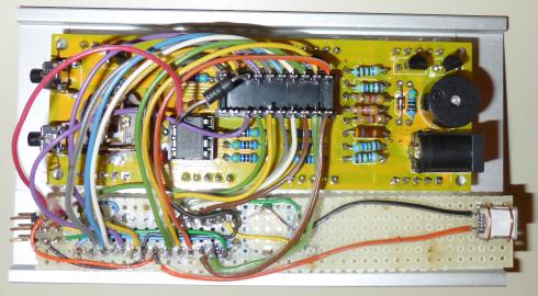
The daughter
board consists of the ATmega88, a power socket, a programming header, a
rotary encoder and a power line decoupling capacitor. I used the
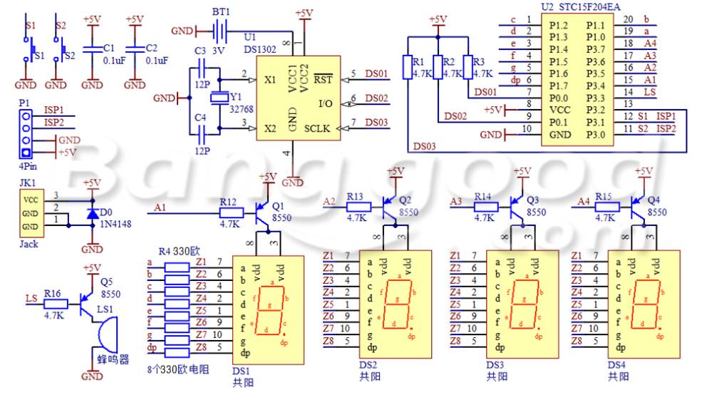
original schematic, just assigning ATmega88 pins to the
functions
that the STC micro controlled.
| STC |
Function |
AVR |
| 1 P12 |
LED-c |
4 PD2 |
| 2 P13 |
LED-d |
5 PD3 |
| 3 P14 |
LED-e |
6 PD4 |
| 4 P15 |
LED-f |
11
PD5 |
| 5 P16 |
LED-g |
12
PD6 |
| 6 P17 |
LED-dp |
13
PD7 |
| 7 P00 |
DS1302
!RST |
16
PB2 |
| 8 Vcc |
+5 |
7 Vcc |
| 9 P01 |
DS1302
I/O |
9 PB6 |
| 10
Gnd |
Gnd |
8 Gnd |
| 11
P30 |
S2 |
nc |
| 12
P31 |
S1 |
nc |
| 13
P32 |
DS1302
SCLK |
10
PB7 |
| 14
P33 |
Beeper |
15
PB1 |
| 15
P34 |
LED-A1 |
23
PC0 |
| 16
P35 |
LED-A2 |
24
PC1 |
| 17
P36 |
LED-A3 |
25
PC2 |
| 18
P37 |
LED-A4 |
26
PC3 |
| 19
P10 |
LED-a |
2 PD0 |
| 20
P11 |
LED-b |
3 PD1 |
|
Enc-A |
27
PC4 |
|
Enc-B |
28
PC5 |
|
Enc-SW |
14
PB0 |
|
ISP 1 |
18
MISO |
|
ISP 3 |
19
SCLK |
|
ISP 4 |
17
MOSI |
|
ISP 5 |
1
!Reset |
|
A/D
pins not used |
20,
21, 22 |
Vcc is applied from the daughterboard to the main circuit
board through a diode such as 1N4001. I found this to be necessary
because without it, the LED displays do not turn on and off properly.
The common anode LED displays are switched using four PNP
transistors, which need their bases driven close to the Vcc rail to
turn off completely. With a Vcc of 5 volts, the ATmega88 output ports
turned on only deliver around 4.3V, insufficient to fully turn these
transistors off. The diode drops the main board Vcc enough so
that the transistors can be driven fully off.
The pushbutton
rotary encoder is a model EC11-1B-18T made by
Changzhou Xinze Electronic Co. It is very similar mechanically and
electrically to the CTS
series 290 rotary
encoder I used before. As a bonus it is easy to panel mount, (as long
as you can find a nut that fits it), and works quite well.
The
decimal point on the last digit indicates PM if on, and AM if off. The
decimals on digits 2 and 3 make up the colon between hours and minutes,
and are always on. The decimal on the first digit indicates whether the alarm
is on or off.
Programming
the clock is simple. Twisting the encoder knob turns the alarm on and off. Press
the
encoder button and programming mode is entered. If the alarm is on when
the button is pressed, the alarm time is displayed and may be
changed. Otherwise the clock time can be set. First hours blink, and
twisting the knob changes the hours. Press the button and minutes blink
and may be similarly changed. Press the button and you return to nornal
clock display. Keep in mind that when clock time programming is
complete, the time is updated in the DS1302 with seconds=zero.
When power is off the DS1302 is powered by its battery, a CR1220
coin cell. Alarm time and setting is stored in EEPROM so it will not be
lost.
*Yes
really. I tried 1K then 4.7K, both too bright in a dark room. Unless
you like an alarm clock+nite light. I suggest that if you build
the kit, use a 16 pin DIP socket in place of the 8 resistors, if it
fits. Then you can use a DIP resistor, then it's easy to try different
values. Update 2017-08: newer versions of this clock kit are available
that have filters that go over the LED display and improve the contrast
greatly. They also figured out how to make the programming buttons
accessible. But programming it is still a PITA, and it forgets all its
settings when the power fails.
Download C
source code for the travel clock
Back
to VE3LNY's AVR Project Page