The last dip-meter I have built uses, in principle, the so-called tunnel diode effect. A tunnel diode is a P-N junction device that exhibits negative resistance - increasing the voltage causes the tunneling current to decrease.
Instead of a tunnel diode, a pair of FET and PNP transistors is used. In this combination, their negative resistance makes them useful in creating an RF oscillator.
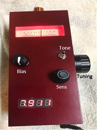
The rest of the dip-meter is typical: coils, meter, tuning capacitor, digital frequency meter followed by buffor, and, in addition, a tone-generator.
The procedure how to use it is as follows:
Description:
P1- 22kOhms - determines the BIAS of the lambda diode and hence the sensitivity of the circuit.
P2- 2,2kOhms - keeps needle of the meter within the scale range.
Set of the BIAS (P1)
-Turn the wiper of the BIAS resistor fully towards the D1 cathode (counterclockwise). The oscillator is not oscillating, and the meter shows maximum deflection – using P2 (sensitivity) keep the needle of the meter in the middle scale area. Turn P1 slowly down up to the point when needle deflection starts decreasing – a sign that the generator starts oscillation. Continue turning P1 to the minimum deflection. It is a point of the proper BIAS and maximum sensitivity of the circuit.
 Measurement of the LC circuit.
Close the Dip meter’s coil to the passive LC circuit and adjust the generator’s frequency. The point when the needle “jumps up” is the resonance frequency of the measured circuit. For more accurate measurements, decrease the coupling of the dip meter’s coil with the circuit under test and tune the oscillator again.
Note: Due to the lambda diode effect (negative resistance), the behavior of the meter is the opposite of the common grid-dip meter, where oscillator frequency is adjusted for minimum deflection (dip). With a lambda diode, we read the resonance frequency when the meter shows MAXIMUM deflection.
|