~~ Year in Review - 2011 ~~ |
|
December
SMCARA Winter 'Pot Luck' Dinner Saturday, 10 December 2011 6 - 9 PM at the Naval Air Museum - - - - - - All hams, their families and friends are welcome to attend
Here is the list (as of 6 December) of who is bringing what: Main dishes: Jim (KJ4WAS) - Ham Pete (WA3UMY) - Pulled Beef Sandwiches Boz (KG3BOZ) - Fried Chicken Dan (KB3UUN) - Turkey Breast Mike (N3KUN) - Hot dogs/meatballs Jim (KB1YZ) - Chili & cornbread
Side dishes: Larry/Lori (KB3ULR) - Deviled eggs Tammy/Tom (AB3IC) - Green Rice Casserole Grant/Rita (W4GMF) - Corn Casserole Pete (WA3UMY) - Macaroni salad Harry (WA3CCL) - Pickled Beets Dan (KB3UUN) - 'Funeral' Potatoes Chris (KB7IAY) - Salad
Dessert dishes: Jim (KJ4WAS) - Cheesecakes (cherry & blueberry) Tammy/Tom (AB3IC) - Cookies Harry (WA3CCL) - Dessert Jim (KB1YZ) - Dessert
What will you be bringing to share? Please contact Pete (WA3UMY) by telephone (301-862-2214) or e-mail (petebutt <at> comfac <dot> com) and let him know so we can post it to this list to minimize duplications of items.
Amateur Radio Exam Session Saturday, 10 December 2011, 10 AM at the Naval Air Museum ------------------- Pre-registration preferred (due to the holidays). Please RSVP with Eric Heard (N3UH) via e-mail at [email protected] or via telephone (301-862-3742) for a NVEC605 form and a questionnaire. Exam location: Patuxent River Naval Air Museum (in the boardroom) Three Notch Road (235) and Pegg Road (by NAS Gate 1) 22156 Three Notch Road, Lexington Park, MD 20653
June
25-26 June is FIELD DAY!
May
April
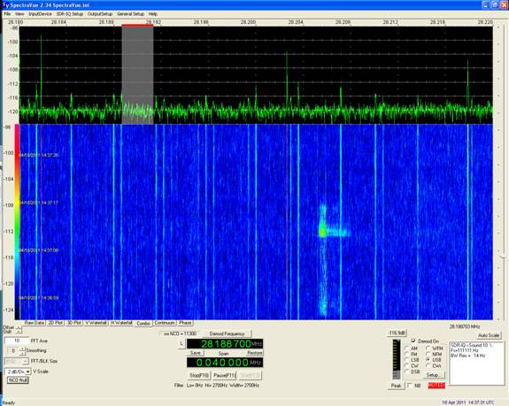
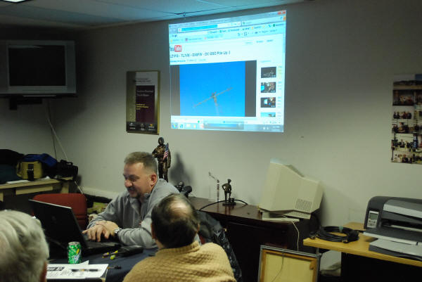
18 April 2011 Subj: Weak Signal VHF Operations Folks,
February KG3BOZ gives us the scoop on sending and receiving QSL cards At our February 24th meeting, Richard 'Boz' Bozovich provided the membership present with an excellent overview of the processes involved with successfully sending and receiving QSL cards to acknowledge making contacts on the air. If you would like to look at his presentation, click [ HERE ] to open the Adobe Acrobat file.
February Exam Session Nets new ham! The Feb. 12 test session had one examinee, Butch Geiger, who passed his Technician exam. Make sure you say hi on the air and welcome him to ham radio. Special thanks goes to our Volunteer Examiners Chris Aberle- KB7IAY, Vernon Gordon -KB3DXT, Gene Talley -N3NO, Jim Smith-N3NV for help with this session. --Eric N3UH
Butch hard at work on the computer taking the Technician Class exam
The final result... a completed CSCE that gets Butch his new ham license
Wiring up an older HF linear amplifier to a newer solid state transceiver Some tips from Tom, W4OKW Here is a nice article (see below) concerning using an external amplifier. This is specific to the Collins 30L1, but applies to Heath SB-200 and similar amps using the 811A or 572B tubes. Any "older" linear amp will most likely need the relay interface to prevent blowing the switching transistor or relay in the solid state rig. All the parts are junque box or radio shack stuff. I built mine in a small R-S minibox and included the 7 diode bias mod in the minibox for a "no holes mod" on the 30L-1. Typical Icom rigs will sink 13.8 volts at 20 mils for the relay. The -170 volts on the amp keying jack will send that little bit of silicon to it's "happy hunting ground"! If you use a honkin' big relay for your box, a transistor driver is easy to include in the interface box. The problem stems from the fact that when these amps were designed, the typical AC line voltage was 110-115 volts, today it runs around 125 or so. I often see 127 at my house. This results in higher B+ on the tubes and more importantly, a higher tube dissipation at idle (PTT exerted, with no RF drive). The way this works is that when unkeyed the amp has -170 on the grids to cut them off. When the keyline (PTT) is grounded, the bias goes to zero and the tubes conduct. Since the B+ is now greater than the 811s were designed for in zero bias operation, they conduct heavily. The result is a lot of heat and the tube's life is shortened. Most amps using the 572B tube don't have the bias problem, it only seems to be applicable to 811A amps. Some of the amps such as the Heath SB-200/201 have a high bias voltage on the keying jack and need the interface box, as do the older SB-220/L-4B/Collins 30S1 amps. I suspect most new amps have been designed for 12 volt keying, but be sure to check the specs before you nuke that nice new transceiver! (This is the big "takeaway" from this ramble!) The 30L1 is a nice amplifier, but getting on in years. A good idea is to replace the existing diode board and capacitor bank with new ones. There are several kits available at a reasonable price. It is an especially good idea if you power up the amp for the first time and fill the house with that rotten smelling electrolytic smoke! You may wind up with an amplifier other than a Collins, but the ideas are worth keeping in the file. 73 Tom
No.2 Amateur Radio 811A
Service Tips for the 30L-1
811A Amplifier The 30L-1 amplifier has been in use from the early '60s. Its users over the following thirty-plus years have included countless military and government organizations, as well as many amateur stations all over the world. Most recently, the S-line (which includes the 30L-1) was recovered from military storage in the United States for use in Operation Desert Storm, because the more modern solid-state transceivers were rendered inoperative by electrostatic discharges produced by blowing sand. Thus the "old vacuum-tube" apparatus came to the rescue during some very trying times. Many remain in use by hams, who must fend for themselves whenever service is required. This article will address some of the more important facets of both design and service. Some common problems and their solutions also will be covered. Times have changed, too: line voltages in general have crept upward, reaching nominally 125 volts, where the amplifiers where designed for 115 volts. In many areas, the nominal 1960 line-voltages were in the vicinity of 110 volts ac. All existing transformers reflect the 115-volt values, and that means, of course, that the 811A's (both in terms of filament and plate supply voltages) frequently are higher than "normal" with today's usual higher voltages. This will result in inordinately high resting current and quiescent plate dissipation. Frequently the resting current in the 30L-1 (unmodified) will exceed the maximum plate dissipation of the tubes. For example: At 1,990 volts on the plates, and without any modification, the resting current was 140 mA, developing 279 watts plate dissipation. According to the 811A data sheets, the maximum dissipation of four tubes is 260 watts ICAS. The following will describe the difficulties encountered in the operation of the 30L-1 as designed, but with current line voltages. It also will cover a number of technically sound solutions, which will be described in detail. Problems and some solutions The 30L-1 as designed, requires: 1. 100 Watt driver - based on a nominal 50-Ohm load 2. 115 volts, ac (source of one of the more serious problems) 3. T/R line (and relay) capable of keying negative 170 volts dc. Most modern solid-state transceivers are capable of keying 12 Vdc at 1 ampere. The 30L-1 requires a sub-system capable of operating the T/R line at the negative 170-volt line (at about 75mA). It therefore requires an interposing relay, keyed by the transceiver T/R line. The contacts of the interposing relay then key the (-) 170-volt line of the antenna relay on the Collins. This is shown in one of the schematic diagrams (see fig. 3) as designed for interfacing with the Icom 751A. Other transceivers are similar. Current power amplifiers utilize antenna relay voltages which vary from 12 Vdc to 115 Vac. Make sure that their needs are met. Things to check Whether the amplifier is your own or someone else's after a long lay-off, or during repair, this is "step one." Do these checks: 1. The voltage at the antenna relay jack should measure negative 170 vdc 2. R28 should measure 47 Ohms. 3. Relay current to ground should be approximately 73 mA (with the 4.5-volt bias module installed) 4. The static plate current will be about 140 mA w/o bias module and about 65 mA with the module installed. Plate voltage will increase from about 1,990 to 2,000 Vdc as you add the 4.5-volt bias module. The addition of the bias module will drop the static plate dissipation from about 278 watts to about 130 watts. (The 811A data show the max. CCS dissipation as 180 watts, and ICAS max dissipation at 260 watts). When servicing a used amplifier, these should be confirmed: 1. Assure that R17 and R18 are as specified; 5 Ohms at 4 watts total 2. C18 should be good, and is the value specified and provided by the manufacturer. Don't "fiddle" with it. 3. The 100 Ohm resistor in the plate leads should be as specified. 4. C22, C23, C24, and C25 all should be 220 pF, 5%. 5. R21, R22, R23, and R24 should be 47 Ohms, 1 Watt. 6. Check R12, 3k Ohms (on antenna relay). 7. Clean tube socket contacts; assure good electrical contact. 8. Assure that F1 and F2 are the correct values. Today's typically higher plate voltage, as it may occur, can be tolerated easily by the tubes, but the extra plate dissipation can't be tolerated. In the amplifier described here a rather novel design, using several forward-biased diodes in the PTT line, was developed for additional bias to reduce the quiescent plate current to the proper value. The PTT line in the 30L-1 carries total grid current, and the forward voltage drop of the diodes produces about 0.6 volts per diode. On the amplifier described here, it requires seven diodes, or about 4.5 volts extra bias. The required extra bias really is determined by the operating plate voltage at any particular location. It is up to the owner to decide how many diodes to use. The criterion here is to develop 65 mA static plate current. There is an advantage in this design, because high-power Zener diodes are becoming scarce. The forward-biased diodes dissipate practically no power. There is an RCA Phono-jack on the back of the 30L-1, and it proved convenient to place the seven diodes in a short length of shrink-tubing, which are in turn soldered to the mating phono plug. It is shown as Fig. 1. In Section IV of Service Tips for the 30L-1 811A amplifier (by Collins), there is important information regarding the filament fuse: "The filament circuit on the 30L-1 is fused by a length of number 30 wire in the center tap ground return of the filament winding on T1. The fuse is connected between the two outer lugs of a terminal strip located near R11 in the rear of the power supply compartment. Under some conditions the amplifier may appear to function normally, even though this fuse has blown; however, this causes hum to appear on the output signal. Check for shorts in the filament circuit." The conduction angle of the 811A's is lowered as the bias is increased, and you will notice that a little more drive will be required, but the amplifier will be slightly more efficient. Final comments The amplifier refurbished here required a set of new tubes. 811A's have been difficult to obtain up to now. The tubes used as replacements are Svetlanas, manufactured in Russia. An interesting sidelight is that four new Svetlana 811A's were more closely matched "right out of the box" than they would be if they were of other manufacture. They also have ceramic bases and ceramic plate-cap insulators, both of which can be seen in the photograph of the 811A on the first page. Svetlana engineers have made certain that the internal alignment and support of the electrodes in the 811A accommodate horizontal placement whenever the design requires it (as they are in the 30L-1), and they have proved to be excellent tubes in both construction and performance. This amplifier has been modified so as to be "better than new." If the directions given in this paper are followed, yours should be, too.
|

 New
K3HKI 2-meter repeater PL tone frequency is 146.2 Hz - program it
in now on the 146.64 MHz repeater frequency!
New
K3HKI 2-meter repeater PL tone frequency is 146.2 Hz - program it
in now on the 146.64 MHz repeater frequency!