
ENGLISH begins after portuguese...please look down
Montando os modulos
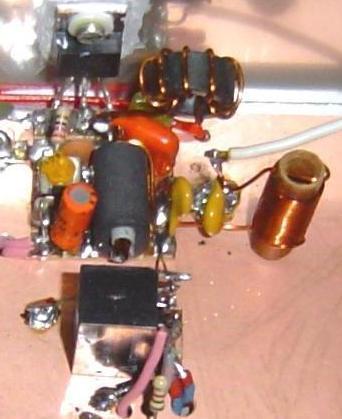
Para montar os modulos precisamos de um placa plano terra, pois o grande segredo do sucesso das minhas montagens é o aterramento.
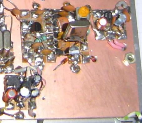
Para montar os modulos do ARARINHA precisaremos de uma placa virgem de tamanho adequado (a ilustrada na foto tem 10x12cm)
Layout da placa :
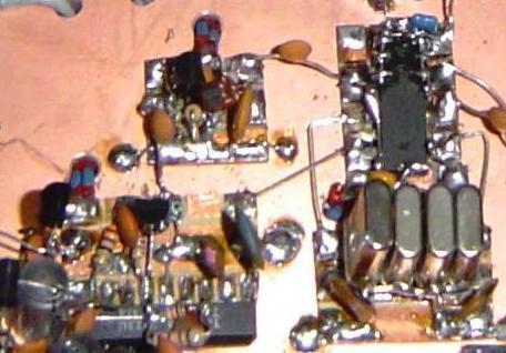
Esta placa é do ARARINHA 5, a parte que esta proxima ao Mixer + B2 é o VFO que nesta montagem é externo.
Note que as interligações foram feitas por traz (ou por baixo), tambem conhecido por montagem em X, o que deixa a montagem muito limpa.
Apos fixar os modulos seguindo as etapas, faça os furos para a passagem dos cabos.
1. Os primeiros modulos a montar são :
amplificador de audio (AF pre + AF)
amplificador de microfone (MIKE)
Modulador/ demodulador + BFO + buffer B1 (TA7358 mod/dem + BFO + b1)
A dispodição do modulos não é critica e pode ser alterada a vontade.
Interligar os modulos conforme esquema, inclusive instale o potenciometro de volume.
Existem 3 tipos de alimentação: +13,8V ou Vcc, +Rx. +Tx, identifique-as utilizando fios de diferentes cores.
procure soldar apenas 2 fios em cada ponto de alimentação e vá assim costurando até o final
TESTE :
ligue provisoriamente o auto falante e o microfone.
alimente os tres modulos
falando no microfone a voz saira no auto falante.
desligue a alimentação do amplificador de audio
Com um rx sintonizado em 10MHz vc deve ouvir uma modulação em DSB e em AM, se vc não modular podera ouvir a portadora que deve estar entre 10,003 e 9,992Mhz.
Com um frequencimetro é possivel medir a frequencia de oscilação do BFO ...meça no pino 7 do TA7358...Normalmente a frequencia muda um pouco devido a carga e/ou capacitancia do frequencimetro.
2. A segunda etapa de montagem
chaveamento CD4053
ladder filter (3x 1/3 4053)
Ta7358 mixer (TA7358+b2)
buffer (B3)
Interligar os modulos conforme esquema, e a fiação de alimentação
Note que a saida do pino 15 do CD4053 para o filtro passa faixa (BPF) devera ser feita com cabo blindado ou um coaxial fino, a ligação da malha deverá ser feita apenas de um lado.
Devera ser previsto uma ilha a mais para soldar a entrada do VFO (cabo coaxial fino ou fio blindado)
Não temos um teste efetivo para esta etapa ....
Estas duas etapas de montagem são basicas para qualquer faixa adotada, em caso de usar em USB e LSB prever um chaveamento no BFO (veja um exemplo desta conexão no projeto BITX40 descrito em outra area do site)
3 Etapa de montagem
Filtro passa faixa (BPF)
Buffer de recepção (BFr)

Apos soldar a alimentação e a interligação é possivel improvisar a recepção.
Testando o RX
Conecte o VFO (não esqueça de alimenta-lo)
Conecte uma antena para 40m (dipolo)
Alimente o Ararainha com 13,8V em 13,8V ou Vcc e tambem em +RX.
Ajuste o BFO para um som rouco não agudo,
sintonize um sinal,
ajuste o BPF para o maximo sinal
sintonize uma estação em LSB
ajuste no BFO e em sintonia para uma qualidade de audio perfeita
sintonize uma estação em CW
com a sintonia indo do agudo para um som grave vá variando a sintonia
ao passar pelo grave abafado o sinal some
continue a variar na mesma direção
o sinal de CW não devera re-aparecer
a menos que seja um sinal muito forte S9+20dB por ex.
Ajustado
Outro metodo de verificar o funcionamento do RX em SSB é checar com uma estação transmitindo em AM. vc tera um apito de portadora constante neste sinal e nas laterais dele vc tera o LSB e o USB, portanto de um lado vc deverá ouvir nitidamente a nodulação e do outro lado da portadora não dara para decodificar.
caso vc não estiver satisfeito repita tudo novamente.
Lembre-se: A qualidade que voce ouve (tonalidade etc) sera amesma que vc transmitirá.
Divirta-se com o RX....
4. Etapa de montagem
Buffer de Tx (BFt)
Driver de Tx (DRV)
Apos soldar a alimentação e a interligação é possivel improvisar a transmissão
Testando o TX
Conecte o VFO (não esqueça de aliment-lo)
Para testar o TX voce vai necessitar de um RX que receba SSB em 40m
Coloque uma carga fantasma de 47 ou 56R 1W (ou mais), não pode ser resistor de fio, mas de metalfilm ou de carbono, nos terminais do frafo de saida do driver.
Instale um adaptador para medição de RF juntamente com um voltimetro
esquema de adapatador para medir RF
Instale um microfone de eletreto.
regule o pot do microfone a terra
Alimente o Ararainha com 13,8V em +13,8V ou Vcc e em +TX
não deve aparecer leitura no voltimetro mesmo em milivolts.
caso exista uma tensão ajuste o resistor com * no esquema
o valor deste resistor é entre 56R ate 4k7 .
caso ainda persista algum sinal maior que 5mV, ajuste o BFO ligeiramente até sumir o sinal.
alguns colegas optaram por colocar um trimpot no lugar deste resistor (recomendo :1K)
----------------------------------------------------------
caso ainda o sinal exista temos alternativas
-pesquisar o tipo de sinal (frequencia amplitude origem)
-caso o sinal seja de muita amplitude sempre ...é sinal de oscilação em alguma etapa.
-alterar o xtal do BFO (refazer o ajuste da recepção)
-alterar capacitores no fiiltro ladder ex 47pF -100pF - 220pf -110pF - 47pF (refazer o ajuste da recepção)
ou me escreva detalhando o problema.
------------------------------------------------------------
Com o sinal zerado na saida do driver ligamos o microfone e regulamos o nivel ouvindo em um rx proximo.
A tensão de RF obtida nestas condições devera estar entre 5 a 10V de RF (5 a 10Vp Volt de pico), o que corresponde a 0,25 a 1W.
Não devemos retocar o BPF na transmissão somente em RX.
Nestas condições fizemos QSOs a 450km de distancia.
5 Etapa
Rele
Amplificador de potencia de RF PA
Filtro PI ou LPF
Note que uso capacitores de 470pF 450V de isolação no LPF ou PI
Interligar os modulos conforme esquema, e a fiação de alimentação.
ATENÇÃO : O unico fio que devera ficar desconectado é o que liga a alimentação do dreno e o positivo.
A alimentação do PA deve ser separada das demais indo diretamente ao positivo na entrada,não faça pontes ou alimente circuitos da linha secundaria.
Ajustes finais
Ligue a alimentação do ARARINHA
Deveremos ter recepção normal.
Ao apertar o PTT o RX devera silenciar.
AJUSTE DO TX
Com a alimentação desligada
Insira, em serie,uma lampada (farol) de automovel com 50W ou mais (farol abixo ou farol alto) entre a alimentação e o dreno.
ainda em serie com a lampada de automovel coloque um amperimetro (4 a 10A) que tenha uma sensibilidade a 10mA (pode ser digital).
A lampada evita a queima do IRF
Coloque uma carga fantasma de no minimo 18W na saida de antena (9x 470R 2W metalfilme em paralelo).
Ajuste o trimpot de polarização do IRF a terra ou zero volt.
Alimente o ARARINHA
monitore a corrente do dreno do IRF
apertando o PTT sem modular
vá ajustando lentamente o trimpot até o IRF consumuir 10mA ou 20mA
modulando a corrente deverá atingir 1A no minimo.
potencia de entrada = tensão VCC X corrente = 13,8 x corrente em A
potencia de saida = 70% da potencia de entrada
para 1A teremos cerca de 10W de saida
para 2A teremos 20W ....
------------------------------
73 de py2ohh miguel
Bons QSOs
Modules Building
To assembly the modules we need a ground plane, the great secret of my homemad radios are the ground.
And the ground plane is a PCB wich we will solder the moidules over.
Layout :
This is the ARARINHA 5 board, next at Mixer + B2 is the VFO in this building it is external.
All connectios are made back side (knowed as X assembly) that does the building plate clean.
After soldering the modules following the steps, make as you need holes for wire jumpers.
1. Step building these modules:
Audio amplifier(AF pre + AF)
Mike amplifier (MIKE)
Modulator/ demodulator + BFO + buffer B1 (TA7358 mod/dem + BFO + b1)
The layout is not critical and you are free to made changes.
Solder all modules in the place and wire all connections like schematics, including the volume potenciometer.There are 3 kinds of power +13,8V or Vcc, +Rx and +Tx, use different wire collors to identify.
Solder only 2 wires in each point and go soldering until finish.
TEST :
Wire the mike and the loud speacker.
Input power in all modules.
When you speaks on mike,you listining in the loud speacker.
Disconnect the power from audio amplifier.
With an external RX tunned around 10MHz (9,990~10MHz) you may listinig your voice in DSB and in AM, if you dont speak you may listining the carrier wich could be between 10,003 e 9,992Mhz.
With a frequency meter is possible toi check the BFO frequency at pin 7 os TA7358. It is normal a little frequncy change because the load and/or capacitance of the meter.
2. Second step of building:
Keying CD4053
ladder filter (3x 1/3 4053)
Ta7358 mixer (TA7358+b2)
buffer (B3)
Solder all modules in the place and wire all connections like schematics.
Note that the output of pin 15 of CD4053 going to BPF will be done with a shielded cable (thin coaxial or other), and the shield will be soldered to ground only in one side.
Glue a small island, near the IC, to solder the VFO input (thin coaxial or other)
We dont have a effective test for this step ....
These two steps of building are basic for other bands desired, in case to change from LSB to USB, you need to use a switch, in the BFO, to change. (in the BITX40 I add LSB and USB please look at this project in this site).
3 Building step
Band pass filterFiltro (BPF)
RX Buffer (BFr)
Solder all modules in the place and wire all connections like schematics.
Rx testing
Connect the VFO.
Connect a antenna for 40m (dipole).
Connect the power supply to 13,8V (Vcc) and to +RX.
Adjust the BFO to listinig a bass sound.
Adjust the VFO to tunne a LSB signal.
Adjust the BPF ro maximum signal.
Adjust the BFO and/or VFO to listining a clear audio.
Find a CW signal.
When you are tunning goes from treble to bass keep tunnig.
When you pass down the bass the audio signal gone.
Keep tunning in the same direction.
The CW signal should not re appear.
It appears if you have a very strong signal S9+20dB par ex.
Remember this is a home made radio !
Adjusted !
It is possible to check the LSB RX also, tunning a AM transmittion, and careffully tunning up or down the main carrier (sounds like a constant frequency) in one side you may listining clearly the modulation, and in the other side no.
------------------------------------------
If you dont like the audioquality repeat all again.
Remember : The quality of the audio that you listinnig are the same wich you will transmitt.
Let the building stopped and have some fun listinning with your new radio ....
4. Building step
Buffer de Tx (BFt)
Driver de Tx (DRV)
Solder all modules in the place and wire all connections like schematics.
RX testing
Connect the VFO
To check the transmitter you need a 40m SSB Rx.
Solder a dummy load (47 or 56R 1W metalfilm or carbon) at the out put of the driver transformer.
Measure the amount of RF, over the dummy load, using a RF voltmeter.
RF volmeter adapter schematics
Connect a eletret mcrophone.
adjust the mike volume trimpot to ground.
Input the power to +13,8V or Vcc and in +TX.
With the voltmeter in mV scale there not appears readings greater then 5mV.
Case the reading is greater then 5mV adjust the 220R resistor (marked with *).
The resitor value can be between 56R to 4k7 (some friends replace this resistor with a 1k trimpot.
Case after the adjustment you have readings more than 5mV adjust carefully the BFO until the 5mV reading (or less) .
----------------------------------------------------------
Case after the adjustment you have readings high than 5MV.
-Search where the signal comes, the frequency etc.
-in case of a strong signal who not changes, may be a auto oscilation in one module. You amy use minor values coupling caps and/or lowing the gain in the module (increasing the resistor value wich are in series with a cap in all emitters transistors)
-Change the xtal of BFO (you need to re do the rx adjustment)
-Change the ladder filter shape changing/addimg caps ex 47pF -100pF - 220pf -110pF - 47pF (you need to re do the rx adjustment)
Or write me describing the troubles.
------------------------------------------------------------
Now with zero RF Volts in the out put of the driver, you connect a microphone and adjust the level listing your modulation in a RX near.
The tension readings over a 50R load will be between 5 and 10V RF (5 to 10 Vp picVolt), wich is 0,25 to 1 W.Never retouch the BPF in transmition only in RX (because you may adjust to a wrong frequency)
Using the ARARINHA at this conditions I made a 450km QSO.
5 Building step
Rele
RF power amplifierPA
PI filter ou LPF
Note that I use 470pF 450V isolation in the LPF.
Solder all modules in the place and wire all connections like schematics.
Attention : A unique wire wich will be diconnected is the wire who connects the main 13.8V to the IRF530 drain.
The power supply to PA will be separated going directly to the main positive, do not use the power at this point to suplly others modules.
Final adjustments
Connect the supplayy to ARARINHA
We listening the normal RX.
If you turn on the PTT the radio RX will be quiet.
TX adjustments
Power supply disconnected.
Isert a car lamp 12V about 50W, and a ammeter (4A to 10A who is able to 10mA readings).
The car lamp is to protect the IRF530 against burnning.
connect a dummy load with a minimum 18W of power to the antenna output (9x 470R 2W metalfilme parallel).
Turnd the bias trimpot of IRF530 to ground.
Turn the power supply on
Always checking the Drain current
Turn on the PTT dont speaks
Adjust carefully the trimpot until the IRF530 current readings reach to 10mA or 20mA
Now speaks ! the current now will be 1A minimum.
We have
Input Power = 13.8V * current (in A)
Output Power = 70% Input Power
with 1A there are 10W output
with 2A .............20W output
------------------------------
73 de py2ohh miguel
es GUD QSOs