ENGLISH begins after portuguese...please look down
Driver (DRV)
Esquema
Material
Placa de circuito impresso virgem de 15 x 15mm
2 Transistores 2N3904 mas pode ser BC547B BC547C BC548B BC548C.
1 capacitores ceramicos 100nF (podem ser entre 47nF e 220nF isolação maior que 25V)
1 resistor de 1k5 1/8W (pode ser 1/4W)
1 resistor de 100R 1/8W (pode ser 1/4W)
2 resistores de 10R 1/8W (pode ser 1/4W)
1 resistor de 33R 1/4W (pode ser 22R ou 27R de 1/4W)
1 bobina enrolada em nucleo de ferrite (ver texto)
Layout
A ligação 2a é aérea.
Montagem
Bobina (Transformador de impedâncias)
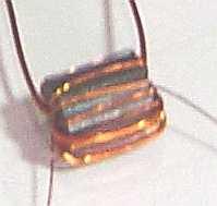
Nota : o diametro dos fios não é importante, utilizamos duas bitolas diferentes para facilitar a identificação, pode-se utilizar fios com amesma bitola.
Núcleo de ferrite tipo N3F3506 (ver site da Sontag) - outros tipos tambem funcionam.
1. Cortar placa e serrar as ilhas
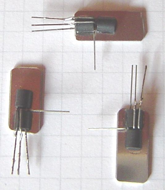
2. Soldar os transistores em paralelo base com base e coletor com coletor, os emissores ficam separados. Os transistores podem (não é necessário) ser fixados, com super bonder, em um pequeno dissipador metalico (5x25mm). Soldar na ilhas 1 (base) 4(coletor) 2 ( um emissor) e 2a(ligação aérea o outro emissor).
3. Soldar resistor entre ilhas 1 e GND.
4. Soldar resistor entre ilhas 1 e 4
5. Soldar resistor (10R) entre ilha 2 e GND / resistor (10R) entre ilha aérea 2a e GND
6. Soldar bobina cuidado com a fase.
7. Soldar resistor entre ilhas 3 e 5.
8. Soldar capacitor entre ilhas 3 e terra (GND).
73 py2ohh miguel
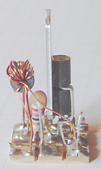
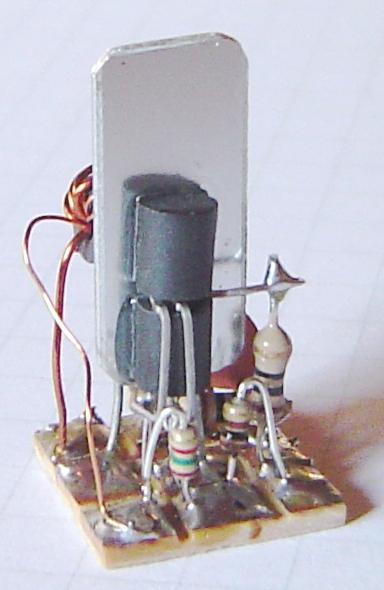
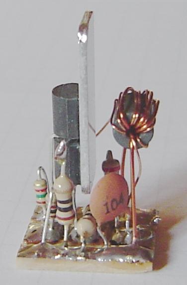
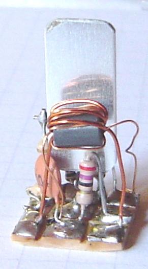
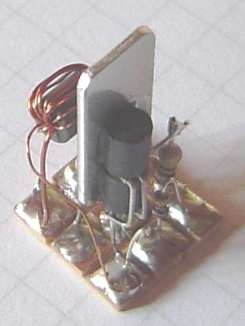
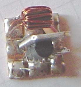
Fotos
Driver (DRV)
Schematic
Parts List
Copper clad PC board 15x15 mm
2 Transistor 2N3904 may be BC547B BC547C BC548B BC548C.
1 100nF (104) Disc cap (between 47nF - 220nF greater than 25V)
1 1k5 1/8W resistor (or 1/4W)
1 100R 1/8W resistor (or 1/4W)
2 10R 1/8W resistor (or 1/4W)
1 33R 1/4W resistor (or 22R or 27R 1/4W)
1 Transformer in ferrite bead (see text).
Layout
The connection 2a is aerial.
Building
Coil (Impedance Transformer)
Note : Wire diameter is not critical,we use two wires gauge to made ease to identify, you may use the same wire gauge.
Ferrite type N3F3506 (ver site da Sontag) - this is not critical and others soft ferrite are OK.
Building
1. Cut the PC board and make islands with a hand saw removing the copper layer.
2. Solder transistors in parallel base with base and collector with collector, the emiters stay alone. The transistors could be glued (fast glue) in a small heat sink (5x25mm). Solder island 1 (base) 4(collector) 2 ( one emiter) and 2a (aerial connection the other emiter).
3. Solder 100R resistor between island 1 and GND.
4. Solder 1k5 resistor between island 1 and 4.
5. Solder resistor (10R) between island 2 and GND / resistor (10R) between island aerial 2a and GND
6. Solder impedance tranformer take care with phase.
7. Solder 33R resistor between island 3 and 5.
8. Solder capacitor between island 3 and GND.
73 py2ohh miguel
Pictures