ENGLISH begins after portuguese...please look down
Modulo do filtro passa faixa (BPF)
Existem algumas formas de montar este filtro, descreverei duas uma excelente e outra pratica e boa.
1. Filtro passa faixa com acoplamento critico indutivo.
Este filtro é muito utilizado em montagens de radioamadores, dá um pouco de trabalho mas tem um resultado excelente. O trabalho esta em desmontar os transformadores de FI e re-enrolar, mas compensa.
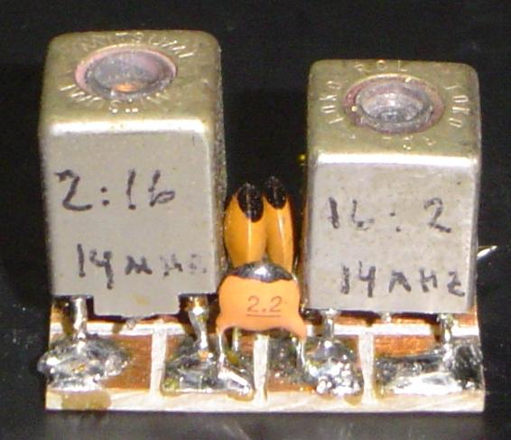
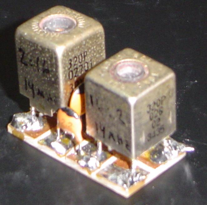
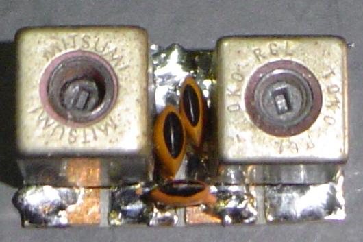
Os transformadores da Toko são encontrados em TVs, videcassete e receptores de FM. Vejam as fotos para identificar. Os de outras marcas tambem servem.
Caso não conseguir estes transformadores veja a solução 2 ou a descrição a seguir.
Esquema
Lista de material
Placa de circuito impresso virgem de 10 x 25mm
2 transformadores de FI Toko ou Mitsumi de 10mm (ver fotos)
2 capacitores ceramicos 150pF
1 capacitor ceramico de 8p2
Layout
===============================================
Como re-enrolar os transformadores
Os transformadores TOKO são do tipo de 10mm de alta frequencia (acima de 10MHz) eles possuem um ferrite de ajuste com fenda pequena (cerca de 3mm). Eles são encontrados em sucatas de radio FM, Televisores, videocassete, autoradios e radios para a faixa do cidadão.
Estes transformadores possuem internamente uma bobina, com nucleo ajustavel, enrolada em uma forma plastica, esta forma é presa a caneca externa de blindagem por quatro pontos prensados.
Para retirar a bobina da blindagem os pontos prensados precisam ser aplainados. Com a ajuda de um estilhete de cortar carpete faça o seviço com muito cuidado.
Depois de removida a forma, corte o fio nos pinos com ajuda de uma chave de fenda de relojoeiro ou o estilhete de carpetes. Caso aja capacitores conectados corte-os (junto aos pinos) e guarde pois são de boa qualidade.
O fio retirado poderá ser reaproveitado.
Importante :
Os enrolamentos deverão ter o mesmo sentido e iniciar nos pontos (lado GND) conforme desenho.
Isto alem de garantir a fase facilitará a montagem.
O fio a ser utilizado pode ser o mesmo retirado da bobina ou outro fio fino (0,15mm de diametro ou menor).
Como enrolar as bobinas
Os transformadores comerciais tem uma distribuição de espiras como no desenho.
apesar dos varios tipos de bobinas e nucleos, a indutancia do enrolamento pode ser calculada aproximadamente:
L (µH) = (16 * (N*N)) / 1000
N = numero de voltas
A variação do valor do indutor é de aproximadamente 30%.
===========================================================
Transformador feito em casa:
Veja a tabela abaixo para o indutor, escolha a forma (raio em mm) e o fio (diametro em mm) disponivel, em amarelo o numero de espiras:
-Tabela baseada em um indutor de 4,7 microhenries
O ideal é escolher fio fino 0,30mm de diametro para menos.
O numero de voltas dado pela tabela sera o do enrolamento com maior numero de voltas, o outro enrolamento sera de 1/5 a 1/7 de voltas deste.
Ex. digamos que um corpo de caneta BIC será utilizado como forma (raio = 3,5mm diametro 7mm) e fio 0,30mm de diametro...pela tabela 28 voltas (27,7) ... secundario 4 voltas (1/7)
Para facilitar a montagem um fio mais grosso poderá ser empregado no secundario, mas atenção os enrolamentos devem ter a mesma direção e o inicio ser ligado a terra.
O esquema será alterado assim :
Ligar no lugar do capacitor de 150pF um capacitor de 68 ou 82pF em paralelo com um trimer de 7-47pF (amarelo) e o layout dependerá do tamanho dos transformadores montados.
Importante as bobinas não poderão ficar paralelas, e sim em angulo reto (ortogonais). Montar uma deitada e outra em pé.
============================================================
Ordem de montagem
1. Cortar placa e serrar as ilhas
2. Soldar um transformador
3. Soldar capacitores de 150pF
4. Soldar outro transformador
5. Soldar capacitor de 8.2pF
Resultados teoricos
Fotos / pictures ARARINHA 20m BPF
Link para BPF na WEB BPF
2. Filtro passa faixa com acoplamento capacitivo.
Este filtro tambem é muito utilizado, apresenta um bom rendimento e é um bom substituto para o filtro anterior.
Os indutores são comerciais ou tambem podem ser enrolados.
Tipo A (modelo utilizado no BITX)
Gráfico teorico do desempenho do filtro
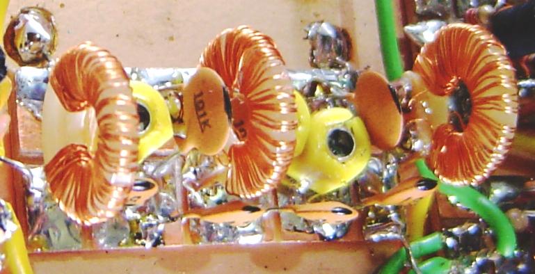
Foto do BPF - BITX40 - utilizamos toroides feitos com botão de roupa.
Tipo B divisor capacitivo
Gráfico teorico do desempenho do filtro
Os indutores poderão ser comerciais, enrolados a mão em toroides ou forma comum com nucleo a ar.
Para os indutores do tipo A, pode-se utilizar a tabela anterior pois os indutores são do mesmo valor.
Para os indutores do tipo B o valor dos indutores é de 6,8microhenries e a tabela é :
Na montagem destes filtros as bobinas não poderão ficar paralelas e sim a 90 graus uma da outra (ortogonais). No caso de toroides isto não é necessário.
English
BPF Module
There are many kimds to build this filter, we describe two one excellent other good and practical.
1. BPF with inductive critic coupling
This filter is most employed in hamradio homebrew, it gives you a little work but it has an excellent result.
The work this in disassembling the IF Tokotransformers and rewinding.
The Toko transformers are found in scraps of TVs, VCRs and FM receivers .
Take a look at the photos to identify they. .
In case that do not find these transformers look to solution 2 or the follow description .
Schematics
Parts list
Copper clad PC board 10x25 mm or bigger
2 10mm IF Toko transformers (lopk the pictures)
2 150pF (151) Disc cap (greater than 25V)
2 8.2pF (8p2) Disc cap (greater than 25V)
Layout
===============================================================================
How to rewind Toko transformers
Transformers TOKO are the 10mm type for high frequency (above of 10MHz) they nave a adjustment ferrite of with small groove(for screew driver adjustment and a size of about 3mm).
They are found in scrap of radio FM, TVs, VCRs and CB radios.
This text are from EI9GQ homepage at http://homepage.eircom.net/~ei9gq/bpf100.html
"All of the inductors were wound on Toko 10mm formers that were recovered from scrap equipment. These transformers are used in television receivers, car radios, CB radios etc. Most of the Toko formers in the BPF were stripped from an old VHF two way radio. The metal screening can on the Toko coils is secured to the plastic base of the coil former by four dimples. They can be flattened by using a carpet knife. It takes a bit of pressure so BE CAREFUL. Once the metal can is out of the way, it is quite easy to remove the copper wire from the former. Use a jewellers screwdriver to break the wire away from the pins, then unwind the wire from the former. If there is a capacitor in the base of the coil, cut the leads off and remove it. Use enamelled copper wire for the new windings"
Important:
The windings will have the same direction and need to start in the points (side GND) as showed in the drawing. This is to guarantee the phase and facilitate the assembly.
The wire used can be the same removed from the older coils or another thin wire (0,15mm of diameter or minor).
How to wind the coils
Commercial Transformers have turns distribution as per drawing.
Although of many types of coils and nucleos, the indutance can be calculated approximately:
L (µH) = (16 * (N*N)) / 1000
N = turns number
This type of coil has a tuning range of about 30%
==================================================
Home made Transformer
Look the table below for 4.7µH inductor, you will choose the form (radius in mm) and the wire (diameter in mm) that you have, in yellow is the coil turns number:
Yellow: Coil turns.
- Table based on an inductor of 4,7 microhenries
The ideal is to choose thin wire 0,30mm of diameter or less.
The table gives you the number of turs of the major winding side, the oyther is 1/5 or 1/7 of that.
Example:
Using a plastic ball pen body as form (radius=3.5mm and diameter=7mm) and a 0.30mm diameter wire, we find in the table 27.7 turns rounding 28, another windig will have 4 (28*1/7).
To made ease the building the wire used in secundary can be thicker, but attention the windings must have the same direction.
New schematics
The new transformer dont has shielding, do not place they in parall. build one laydown and other as normal (standup).
Building
1. Cut the plate and saw the islands
2. Solder a transformer
3. Solder a 150pF cap.
4. Solder another transformer
5. Solder a 8.2pF cap
Simulation
Pictures ARARINHA 20m BPF
Web BPF link BPF
2. BPF with capacitive coupling.
This filter is also very popular and is a good substitute for the previous filter.
The inductors are commercial or tambem can be wond.
Type A (same used in the BITX)
Simulator results
Picture BITX40 BPF built with dresses bottons as toroidal form.
Type B with capacitive divider.
Teorichal performance graph of the filter
The inductors could be commercial, wound by hand in toroides or common form with air nucleos.
For the inductors of the A type, the previous table can be used therefore the inductors is of the same value. For the inductors of type B the value of the inductors is of 6.8microhenries and the table is:
In the assembly of these filters the coils could not be parallel they need to be at 90 degrees one of the other.
If they are like toroides this is not necessary.