|
·
1 Phase ( Delay ) Coax ( or Tube ) Line Length
If you would
use a coaxial relay ( to switch LHCP or RHCP ) in combination
with this configuration
( the impedance of the first phase delay line, red colored, is
in this case for instance 104 Ohm if both antenna impedances are
52 Ohm ), you take the Phase Line Coax Length
( 52 Ohm, same as the antenna impedance, the characteristic impedance
of this coax delay line has to match the antenna : otherwise it
would work as an impedance transformer which is unwanted here
). You can place it between one of the antennas ( dipoles ) and
an impedance transformer ( 73.5 Ohm ). Also, see this
page.
Remark. If
your crossed yagi's antenna has a physical offset, resulting in
a delay of exactly 90 °, recommended for such a yagi system,
( working satellites ), then a phase line is not used anymore.
Now you need only two coaxial cables ( with the same length !
), necessary as transformers.
Concerning
the high frequencies, a perfect balance has been reached with
respect to the power devided over the two antennas. And it 'interferometer'
behaviour of a crossed yagi's antenna ( single
or concentric boom construction ) is nearly ideal. A very good
combination. See also what I write here
concerning interferometer phenomena ( concerning dual
or cross boom constructions ).
I made this
script on request. It concerns crossed yagi's antenna's where
the physical offset is not only 90
°.
·
2 I often used the WiMo configuration, also for the home made
antenna's I built. All worked well :-).
·
3 If a Impedance Transformer has been needed, use it together
with the Phase Cable. Attention !
For Match Cables use only the Factor
1, 3, 5 ( max 7 ) the lower, the better !
Remark ! In
this script you also can input even, negative or not rounded values
for ( possible ) other calculations :-). But in case of Matching
Lines only use odd values ( multiples ) !
================================================
Dutch Text
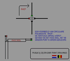
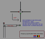
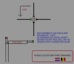
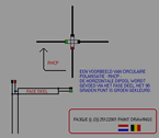
: find CP sense : LHCP and RHCP
Nog een beetje
info, algemeen.
RHCP of LHCP
: het is uiterst simpel om de draairichting te bepalen : kijk
vanaf de reflector zijde van de antennes
welke antenne via de fase leiding gevoed wordt, is dit de rechtse
antenne : RHCP, is het juist de linkse antenne : LHCP .. makkelijk
nietwaar ?
Zijn de
aansluitingen omgewisseld ( 'ompolen' van de
antennes, in tegenfase ), dan betreft het respectievelijk LHCP en RHCP. Zie
ook hieronder.
Ik heb enige
tekeningetjes gemaakt ( zie de thumbnails hierboven ) als hulpmiddel. Zo kan
men steeds gemakkelijk de richting bepalen. Zie ook de bijgevoegde
tekst.
Kijk eerst
bij welke antenne het 0 ° punt ligt, kijk dan bij welke antenne
het 90 ° punt ligt. In bovenstaand voorbeeld, het 29.0 °
+ 61.0 ° = 90 ° punt betreffende ( gradenverdeling antenne
boom ). De tweede dipool ligt 29.0 ° voor de eerste dipool.
De fasekabel zal 29.0 ° + 90.0 ° zijn. Volgens de WiMo
methode.
Het 0 °
punt vind je bij die antenne waar
de voeding direct is. Het 90 °
punt vind je bij de andere antenne die dus gevoed wordt via de
faseleiding. Als nu dit 90 °
punt rechts van het 0 ° punt ligt, vanaf de achterzijde
gezien van de antenne combinatie, is er sprake van RHCP.
Het moge duidelijk
zijn dat de genoemde 0 en 90 ° punten een aansluiting
( dipoolhelft ) van de bedoelde antenne betreffen .. zie de tekeningen
( rode en groene aansluitingen ). De rode en zwarte
( groene en zwarte ) aansluitingen bepalen mede de CP sense.
Bij een kruisyagi
hoef je maar te kijken waar de coax kernen worden aangesloten.
Je ziet ook meteen dat een antenne die in de afstraal richting
RHCP oplevert, in de tegenovergestelde richting LHCP signalen
produceert.
Naschrift.
Ik maakte dit scriptje op verzoek. In verband met meerdere vragen
van enkele mensen.
Het betreft kruisyagi antenne systemen waarbij de fysieke offset
geen 90 ° fase verschuiving
veroorzaakt. Een en ander kan dan wat onoverzichtelijk lijken
ten aanzien van het aansluiten. Indien uw kruisyagi een fysieke
offset heeft, resulterend in een delay van precies 90 ° (
aanbevelenswaardig ) dan komt een coaxiale fase lijn ( vertraging
) te vervallen. Je hebt dan alleen nog maar de twee coaxiale kabeltjes
( van gelijke lengte ) nodig die
de trafo's vormen. Er is ( met name op hoge frequenties )
een perfect evenwicht bereikt ten aanzien
van de powerverdeling naar de beide antennes. En daarbij is het
'interferometer' gedrag van een kruisyagi erg goed. Een mooie
combinatie dus .. Zie ook ( bij interesse ) wat ik er hier
( ALON / ALAT, squint en nog iets over skewed design yagi's )
over geschreven heb.
|


