I had made a 23cm transverter in the past and it was based on the UHF Unterlage design from Germany. It could deliver about 400mW RF output.
As I wanted to make contacts outside of The Netherlands, I had to make an RF amplifier, put up a Yagi antenna and also needed to place a preamp.
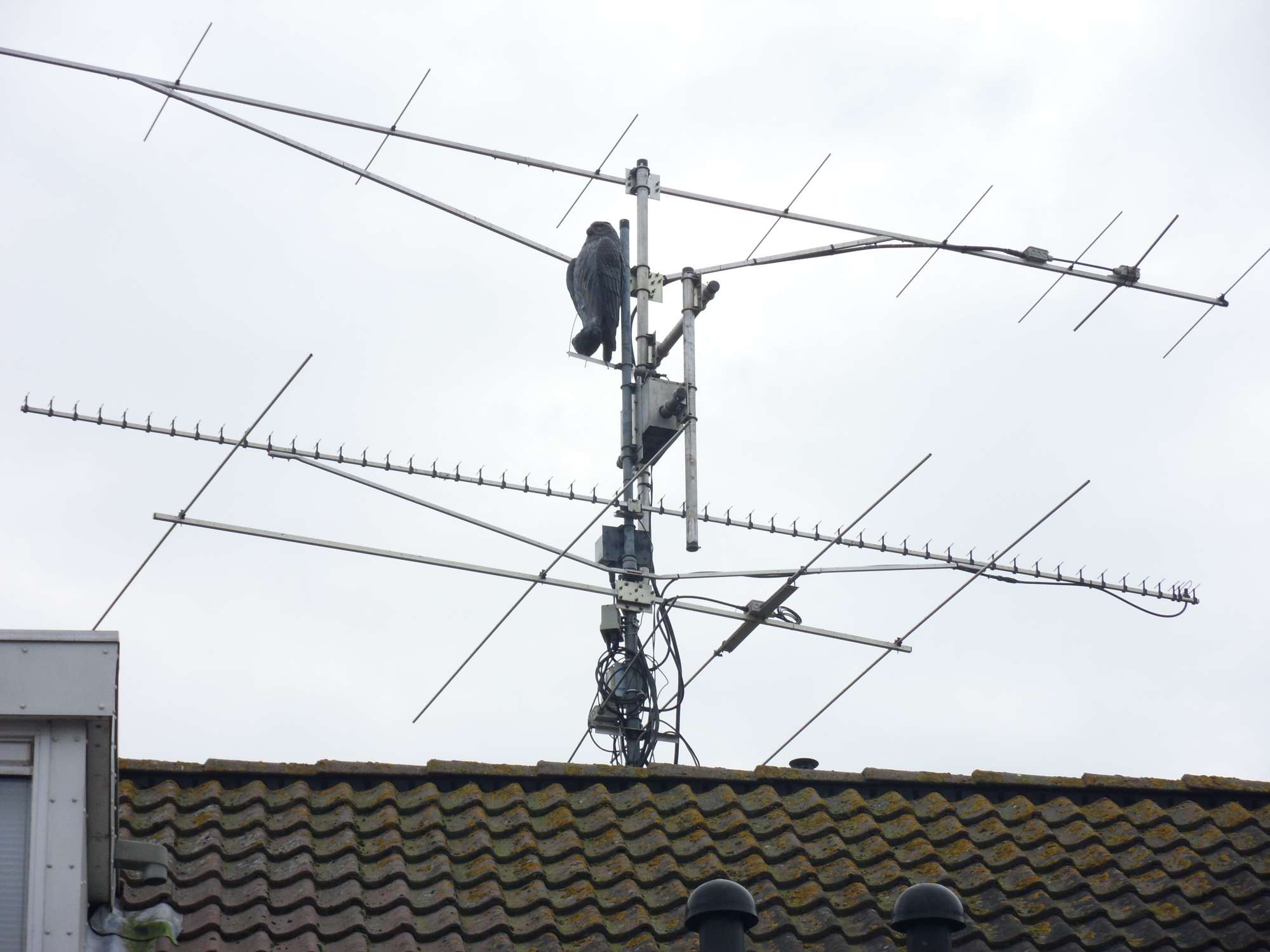
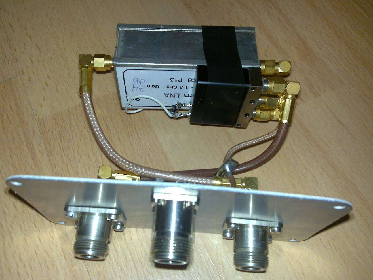
The Yagi was the easy part and searching the local internet pages I found a 55 element Tonna and a former 23cm ATV preamp with a gain of @34dB.
After adjusting it to 1296MHz I got about 26dB gain and a noise factor of 1dB
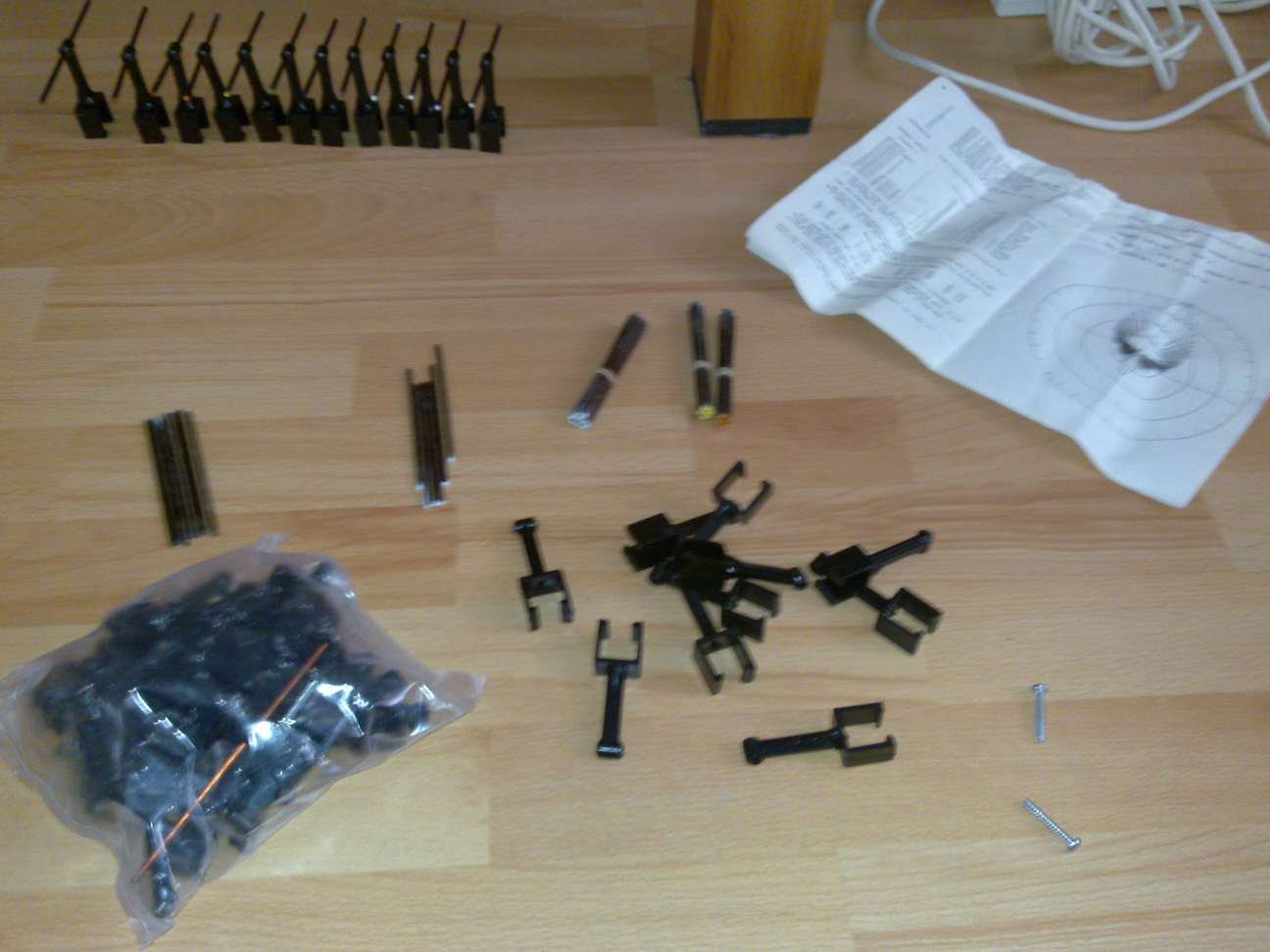
Putting the 55 elements together was a lot of work, hammering the litte copper elements in their plastic boom-holders and measuring each side to be symmetrical ...pfff what a work.

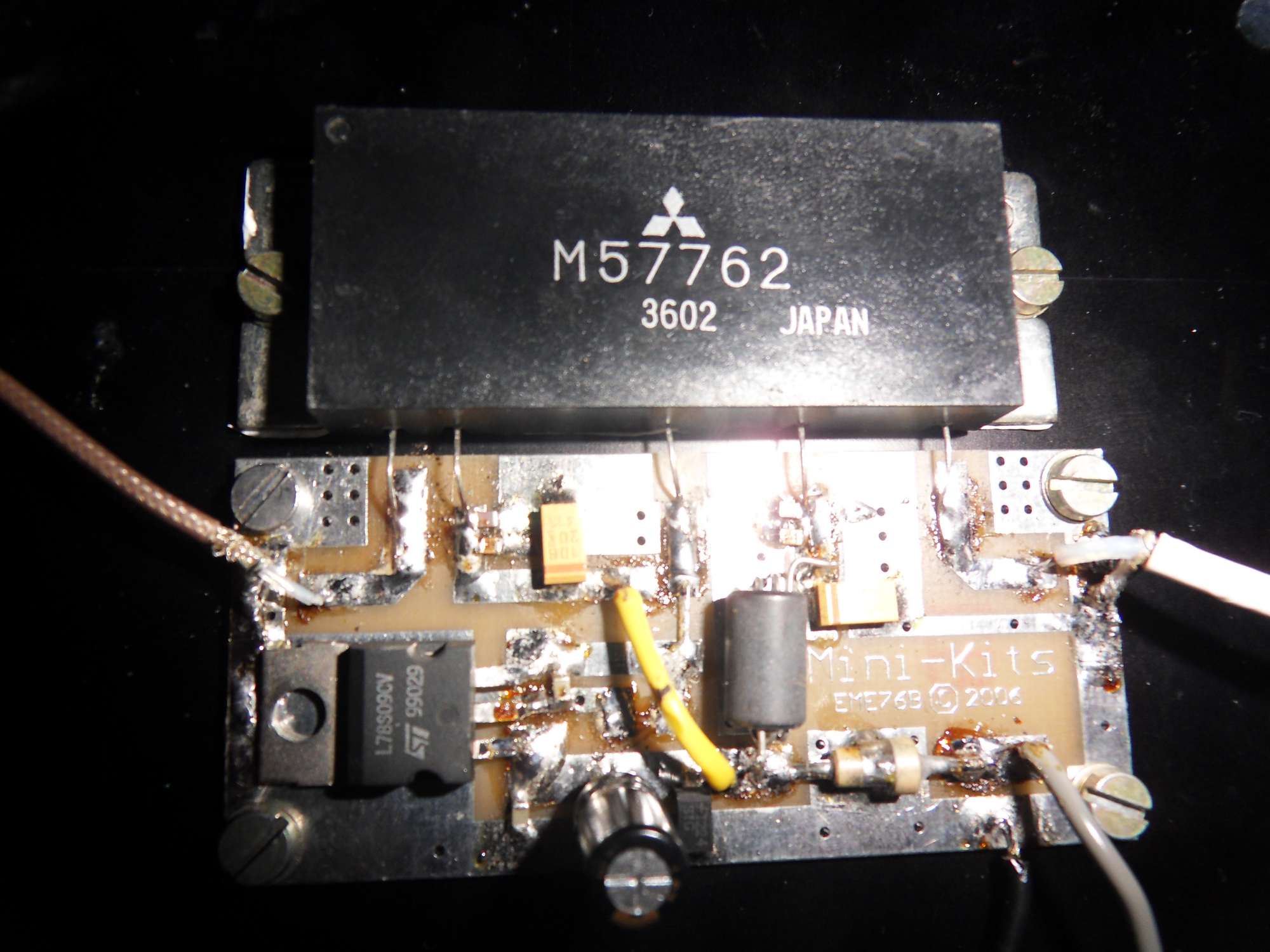
Now for the amplifier part. I tried using 2x BFQ69 parallel but this was not satisfactury. Eventually I purchased a Mitsubishi power module M57762 which can give 18W maximum.
I did not choose for the new RA-type version because biasing this "brick" was a bit tricky. You need a bias voltage for SSB work.
The old type module needs a fixed voltage and that made things easy ...only that it is not made anymore and you have to get lucky to find one ...mine cost 75 euro.
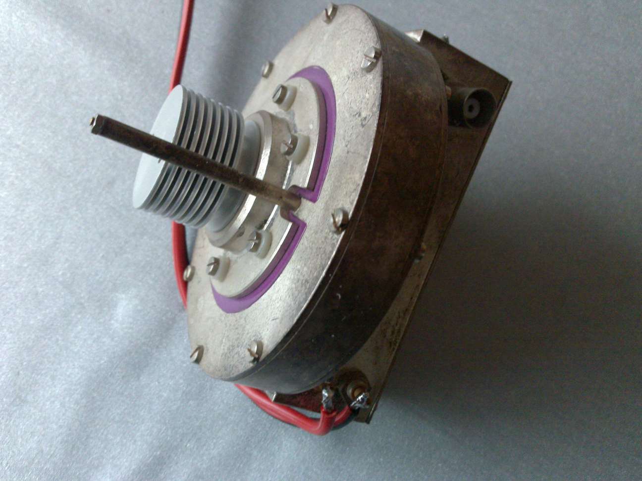
But as one could guess the output was not shokking. I wanted more. Searching the local internet sale pages I found a 23cm cavity ...yep already made and included a 2C39BA tube (or valve as some would say).
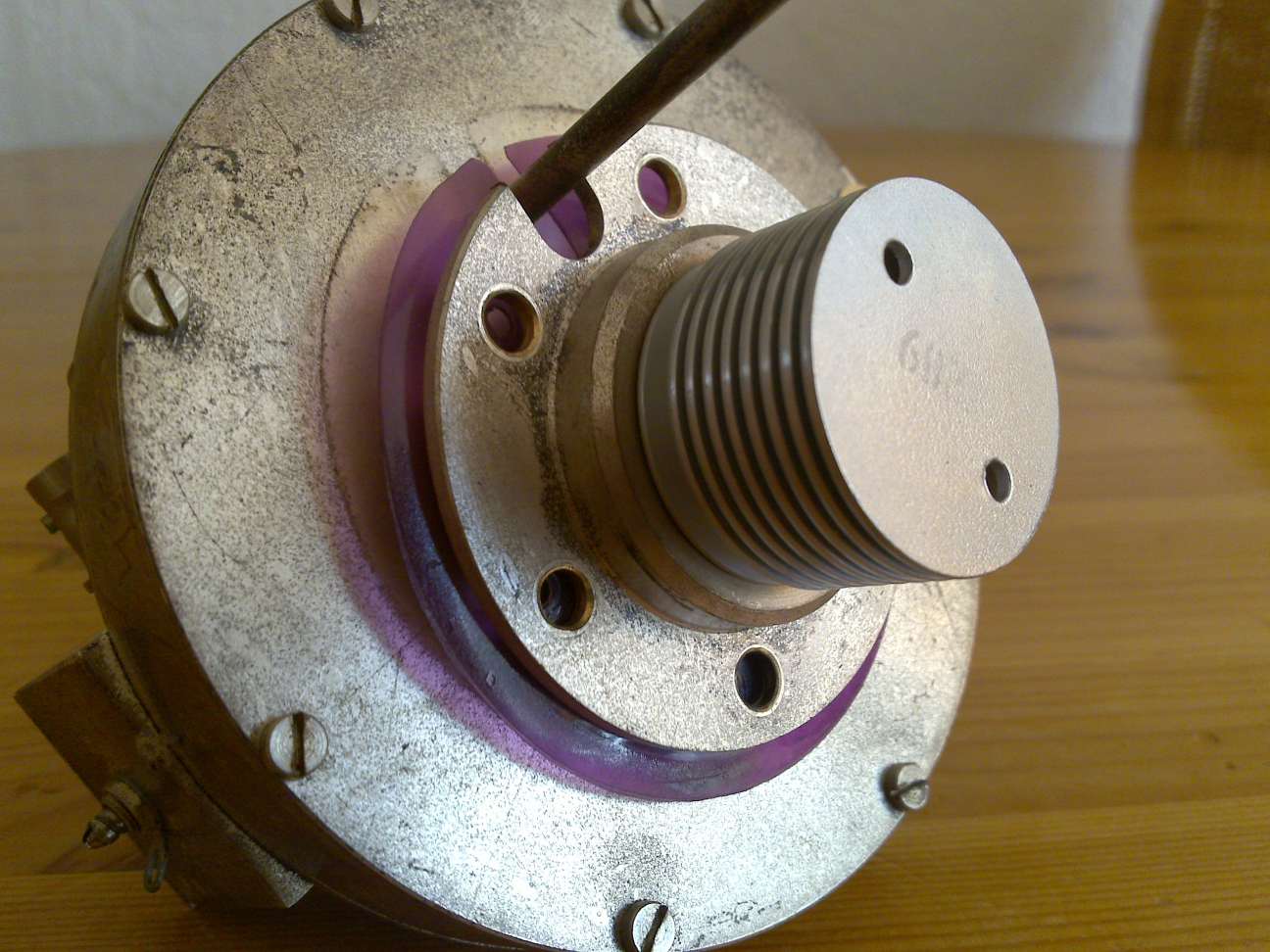
It looked allright but what did I know :-)
First of all I searched in books and Googled some time to find out that good information about a 2C39 amplifier was hard to find. Specifications like maximum anode voltage and heater voltage was different on each page I found.
Eventually I found out that the anode voltage should not exceed 1200 Volts. The heater voltage should be about 6 Volts and the current in standby mode should be 30 mA.
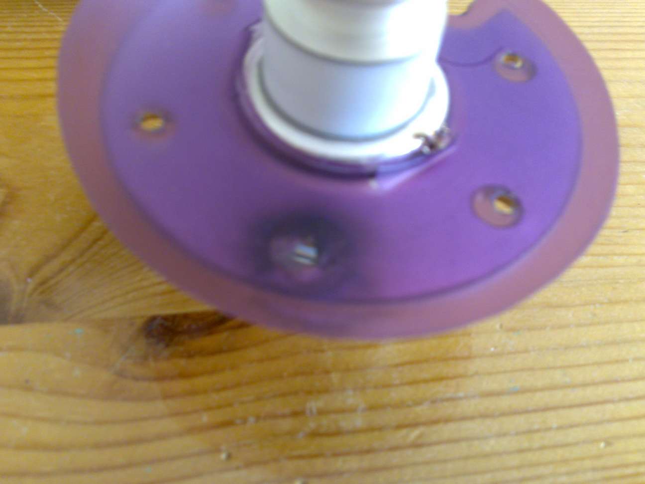
The original anode isolation was some kind of purple plastic stuff. All looked good and after heating for 2 minutes (really needed to warm up the tube) I applied 1200 V at the anode ... KABOOM !
Damn, that made my heart miss a beat. The purple garbage was some kind of plastic which could not stand high voltages. I had to replace it with a white Teflon sheet. The screws to hold the anode plate were also replaced by Teflon types, just to be sure all would not explode.
This cavity also needed some mechanical work as it was not to be tuned easilly ...thanks to Jos PA3ACJ it was modified.
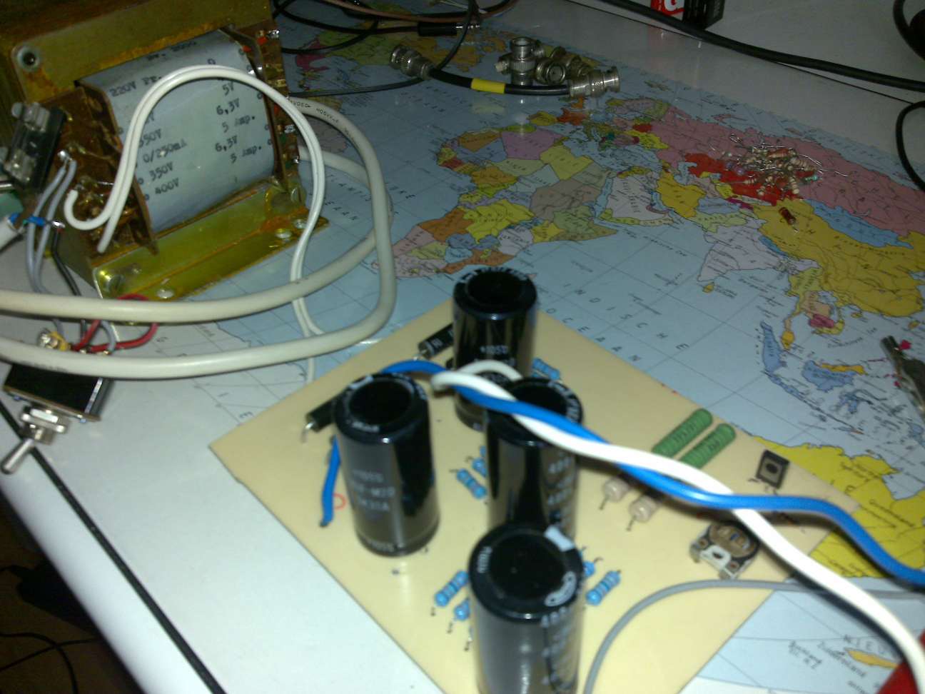
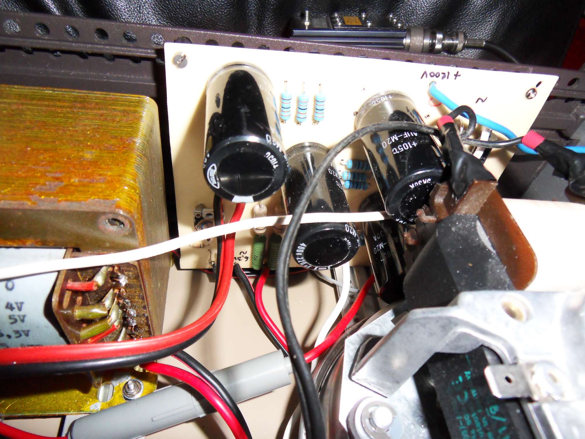
The power supply for this amplifier was actually rather easy to make. I purchased a transformer via the internet (what would I do without internet) 2x 400 Volt / 250mA and with the comming of microwave ovens, you can use 4x 15kV diodes to make AC to DC and use a high voltage fuse from...yes again the microwave oven.
I did not steal them from our own microwave in the kitchen as the wife would not be amused, so ebay was the solution and the postman delivers at home,so no need to get out of the chair.
The high voltage capacitors 450V could also be purchased via ebay, but I had ripped them out of an old switched power supply.
By putting 4 of these capacitors in series with parallel bleeder resistors, you can double the voltage to the value you need.
The bleeder resistors are needed to unload the capacitors, otherwise the high voltage would be on your system and if you want to fiddle around you would get an electric shock .... yes I know all about it.
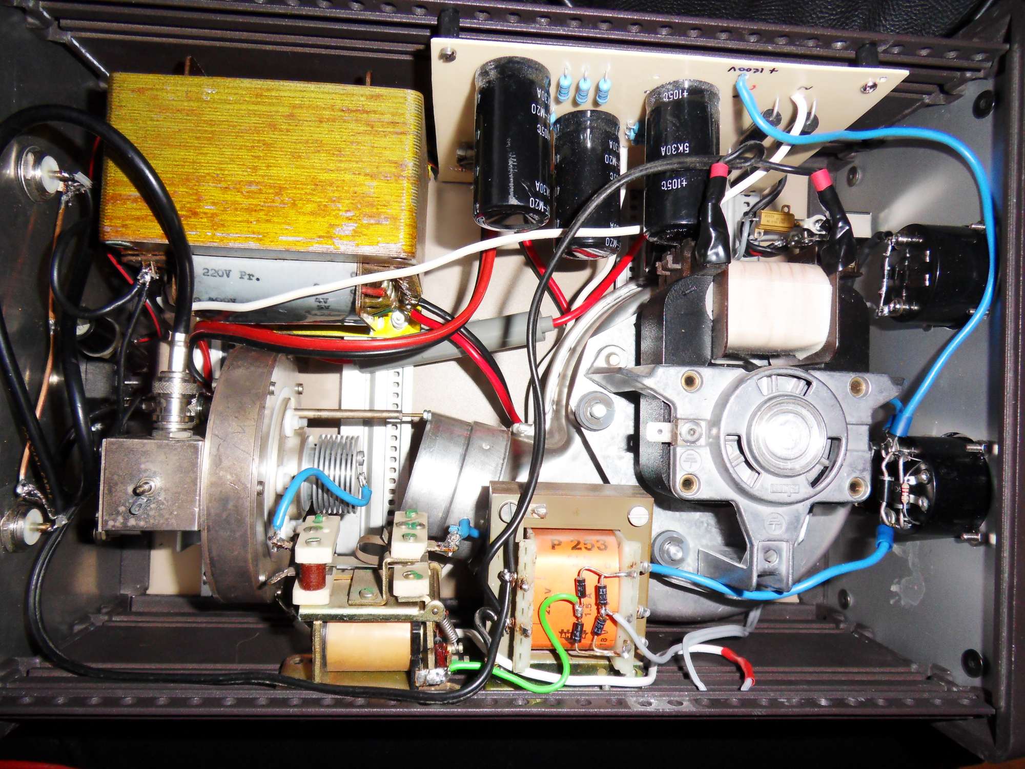
Extra cooling is needed to get rid of the heat when pushing the 2C39 to its limits. A horn blower was placed for this purpouse.
On the front panel I placed a meter for anode voltage and current. This to see if the bleeder resistors do their work and to check if the current in TX mode would be allright.
I used normal 1mA meters and shunted them for this purpouse. Info about shunting mA meters to measure voltages can be found on the internet.
When tuning the cavity I found that the needed input was 4 Watts, the output then was approximately 90 Watts and the anode voltage dropped to 1000 Volts with about 120 mA anode current. This is slightly more than the advised 100 mA on some web sites.
Now for the real work ...making qso's. In the oktober 2010 UHF / SHF contest I made 11 qso's with the best distance to DR9A over 471 km.
Unfortunately my 55 element Yagi is 1 meter above the roof and the antenna looks into trees and high buildings which surround my house.
For real DX the antenna should have free vision in 360 degrees and the higer the better !
You can also consider using a dish, but on 23cm it is still a large contraption of about 2.4m diameter. A dish is something amateurs use from 13cm and higher, unless you plan to do EME and have a big back yard.
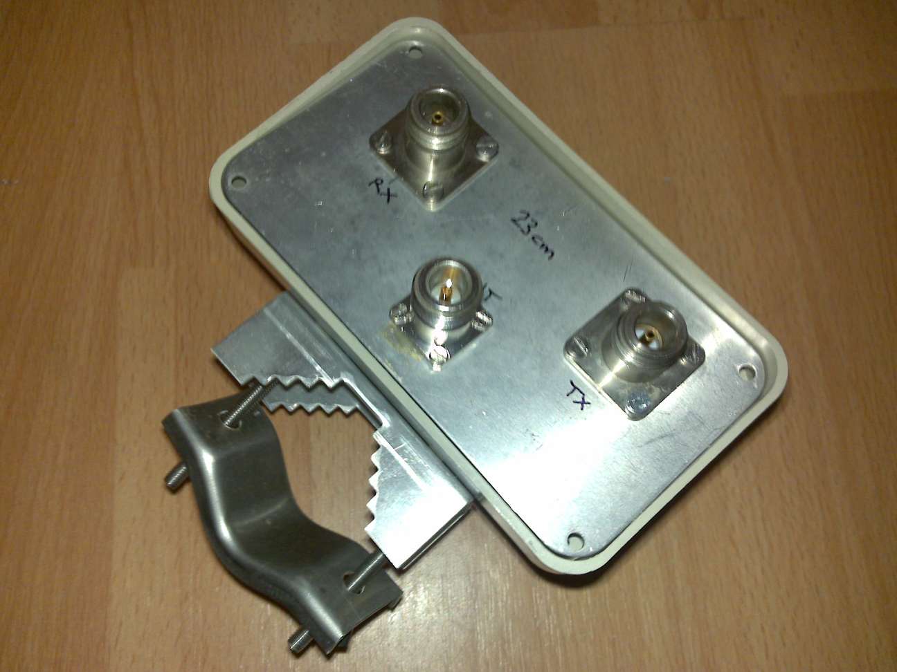
Here are some pictures of the 23cm preamp and coaxial relay.
Some audio recordings of my first 23cm qso's on 2 and 3 oktober 2010, at the UHF-SHF contest in europe:
TR QSO with PA0EHG
TR QSO with DF0OL
TR QSO with DF0MU
TR QSO with PA6NL
TR QSO with PA3AWJ
TR QSO with PA0EZ
TR QSO with PA0S
TR QSO with G3XDY
TR QSO with DK0PU
TR QSO with PI4GN
TR QSO with DR9A
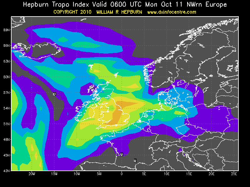
On 11-10-2010 we had a major Tropo duct from PA to G, GI, GW and OY. Amazing signals comming from s2 to s9+60 dB.
Below the qso's I made, with best ODX 1299 km to OY9JD !!!!
Tropo map from Hepburn showing the area between the UK and Europe:
Home