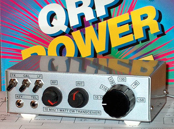
"NiceRig" 40-30
10 MHz CW transceiver 1 watt QRP,
the 40-30 designed by NE-QRP club
(1998)
KLIK HIER VOOR DE NEDERLANDSE VERSIE
Favourite QRP transceiver
Favourite QRP transceiver
This is my favourite QRP transceiver and that's why it has it's place on my website.
The design is published in the ARRL book "QRP Power" and I do recommend you to buy it and read
the articles about the modifications carried out by enthusiast experimenters. It was also
published in QST of November 1994.
The rig is designed by the NE-QRP club as a club project. The original name for the rig is 40-40,
a rig for 40 meters and cost to members was 40 dollar. I made the 40-30 version, indeed for 30 meters.
The original is a very nice design with full break in and I added some extra's to it:
Band filter with two tuned circuits at the receiver front end to improve image rejection.
Extra crystal in the IF filter (not really an improvement).
Extra LF amplifier for a loudspeaker.
Rit control.
LF switch for high / low LF gain.
Frequency marker generator for 10 kHz marker signals.
Some other not so important modifications.
Circuit diagram, part 1
big diagram
The design
The design is straight forward and I do not think that you need a further explanation. If you
want it, please read the book or QST.
The receiver is a superhet with an IF of 8 MHz. The VFO range is from 2.1 to 2.15 MHz.
Tuning is done by a single potentiometer, if you use a big knob, you do not need a
10 turn.
All fixed inductances are standard available types (like big resistors). The variable ones are
wound on 6 mm cores.
It was not so easy to align the 8 MHz TX crystal oscillator exactly at the center frequency of the
crystal filter. I needed an oscilloscope for that. That is why there is a 15 pF / 4.7 uH circuit
in series with the 8 MHz crystal. You have to select these values for your crystal.
After alignment of this 8 MHz TX oscillator, adjust the BFO for an 800 Hz audio tone when transmitting.
In my version, a 4.7 pF capacitor in parallel with the 8 MHz BFO crystal was required
to adjust it to the correct frequency.
The side tone level can be varied by changing the value of the 4M7 resistor in the mute circuit.
If the RIT is at zero position, you are exactly on frequency when the audio tone of the other station
is equal to that of the side tone!
Circuit diagram, part 2
big diagram
Notes
Built via the ugly method (dead bug method). Parts are soldered at both sides of the double
sided unetched print.
The VFO coil is wound on an iron core T50-2. For better mechanical stability, do not mount the
iron core so close to the metal housing as I did.
I used 3 transistors 2N4427 in parallel in the final stage because I had quite a lot of them.
But it is also possible to use one 2N3553.
DO NOT USE A 78L05 AS STABILIZER BUT A 7805! 780X TYPES ARE MUCH BETTER THAN 78L0X VERSIONS!
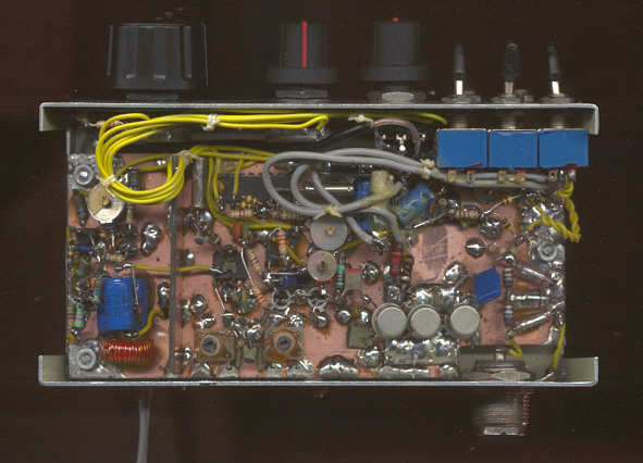
Inside the transceiver
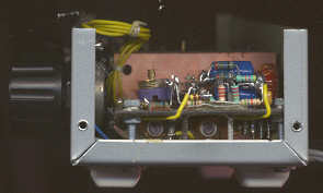
Both sides of the unetched PCB are fitted with components
Performance
Sensitivity: 0.25 uV signals are readable
3rd intercept: 3 dBm
Sideband suppression: 36 dB
Spurious responses: 5.87 MHz: -58 dB; 8.0 MHz: -59 dB; 12.25 MHz: -92 dB; 14.37 MHz: -84 dB
RX current: 20 mA
Transmit power: 1 W at 9 V; 1.5 W at 12 V; 2 W at 13.8 V
Suppression of spurious emission: below 30 MHz: 43 dB, above 30 MHz: 55 dB
BACK TO INDEX PA2OHH