A simple, solid rig for outdoor use during Holidays.
More is possible with this solid QRP rig than you should expect.
Just try it and do not give up soon!
"HappyHolidays TRX"
A four band VXO tuned
1 watt QRP CW transceiver
KLIK HIER VOOR DE NEDERLANDSE VERSIE
A simple, solid rig for outdoor use during Holidays.
More is possible with this solid QRP rig than you should expect.
Just try it and do not give up soon!
The "HappyHolidays" is a 4 band 1 watt VXO controlled transceiver, with similar performance but with more recent components and better suppression of AM detection and also intended for Holiday use. It was an experiment to make a 4 bander. But now I would have preferred a 2 or 1 band transceiver, there are so many switches on the 4 band transceiver.

Circuit diagram
R1 is the 1200 ohm resistor just below the pin Utx
big diagram
Mixer
The mixer is one C-mos switch of the 74HC4066 (Do not use a HCT!!!). It works perfect!!!
Adjust the 5k potmeter for minimum AM detection of strong broadcast stations. If you do not have an AM signal available for adjustment, set it to centre position.
LF amplifier
Just a simple 3 transistor amplifier. The first transistor is muted during TX via the 10k resistor. The LF amplifier is optimized for CW reception with a low LF beat tone. The selectivity of the ear is very good for low audio tones up to 600 - 800 Hz, a CW filter is not really necessary.
Select the value of R1 (1200 ohm) so that in receive mode, the supply voltage of the 74HC4066 (pin 14) is approximately 5 V.
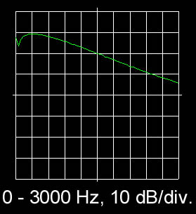
The LF amplifier is optimized for CW
but it is not a very narrow CW filter.
| Tuning ranges without the optional series inductors | ||
| Crystal Frequency (kHz) |
Minimum Frequency (kHz) |
Maximum Frequency (kHz) |
| 7025 | 7024.3 | 7026.2 |
| 10125 | 10123.7 | 10126.5 |
| 14050 | 14048.2 | 14051.9 |
| 18080 | 18076.6 | 18080.4 |
| Tuning ranges with the optional series inductors | ||
| Crystal Frequency (kHz) |
Minimum Frequency (kHz) |
Maximum Frequency (kHz) |
| 7025 | 7021.1 | 7023.8 |
| 10125 | 10118.4 | 10123.0 |
| 14050 | 14039.9 | 14045.9 |
| 18080 | 18070.6 | 18076.4 |
Transmitter part
The VXO signal is buffered by a C-mos switch and amplified to 1 watt by a transistor 2N3553 or as I did, 2 transistors 2N4427 in parallel. The 1k ohm resistor makes the amplifier more stable when mismatches occur. The 0.68 uH / 180 pF and 0.47 uH / 68 pF are tuned to the second harmonic of 7 resp. 14 MHz for extra suppression.
Options
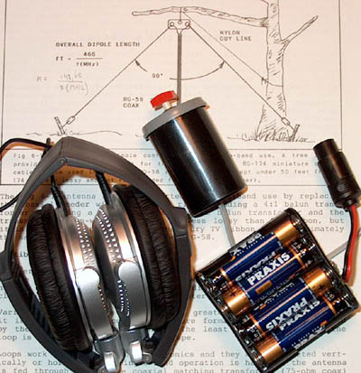
Foldable headphones, a simple key and batteries.
Notes
Built via the ugly method (dead bug method). Parts are soldered at both sides of he double sided unetched print.
Inductances are commercially available types looking like big resistors.
Do not use a HCT type but a HC type!
Performance
Sensitivity: 0.6 uV signals are readable
3rd intercept: more than 20 dBm
Spurious responses of the receiver: Better than -90 dB
RX current: 10 mA
Transmit power: 0.5 W at 9 V; 1 W at 12 V; 1.5 W at 13.5 V
Harmonic suppression: below 30 MHz: 43 dBc, above 30 MHz: 60 dBc
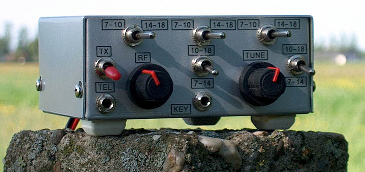
Position of switches and other controls
50 Hz or 100 Hz hum of a direct conversion receiver
The rig is designed for use with a battery supply.
When you use a power supply connected to the mains, it is possible that you will hear some 50 Hz / 100 Hz hum due to Local Oscillator leakage from the mixer to the antenna. This depends on the antenna, frequency band and power supply you are using. A lot of Direct Conversion receivers have this problem.
To overcome this problem you can add the RF preamplifier as is given here below at the 21 MHz version. Increase the 270 ohm emitter resistor if the sensitivity is too high.
Not all preamplifiers do suppress the Local Oscillator leakage from the mixer to the antenna. The first version of the preamplifier without the second transistor in the collector did not suppress the LO leakage and also an emitter follower was not usable.
PHOTOGRAPHS
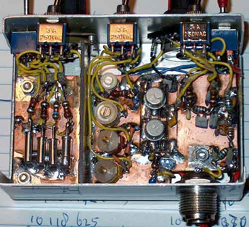
Inside the box. The VXO is screened from the
rest of the circuit by a verical piece of PCB.
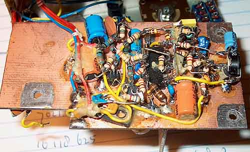
Both sides of the unetched PCB are fitted with components
21 MHz version with RF preamplifier

Schematic diagram of the 21 MHz version with RF preamplifier
big diagram