Student electronics.
TUBE RECEIVER WITH EC92
(1973)
KLIK HIER VOOR DE NEDERLANDSE VERSIE

Student electronics.

|
 Barefoot to Amsterdam. Then you had trains with real locomotives! |
Some classmates were radio amateur. Friendly people who spend the whole day with talking about radio. They bought expensive two-meter transceivers and large, heavy shortwave receivers. But I wanted simplicity preferred to play with a crystal receiver. Listening to the shortwave broadcast stations during many hours was nice. Listening very simple to radio amateur with a simple regenerative receiver for 80 meters. With a tube, such as was used in the early days of radio! Indeed, I wanted to build such a receiver!
It had to be a receiver that easily would fit in a plastic bag to take it everywhere. There were still some parts and a EC92 tube left from experiments with illegal transmitters. It became a simple regenerative receiver with triode EC92 and a crystal phone. And with fine tuning. The control of the regenerationk was perfect. You could adjust it right on the edge of generation. Or slightly over it for optimum reception of weak SSB stations. And oscillating quite strong for strong SSB stations. The real historical radio sensation. A wire of 5 m along the rafters of my hired student room as an antenna. And the bed was used as ground.

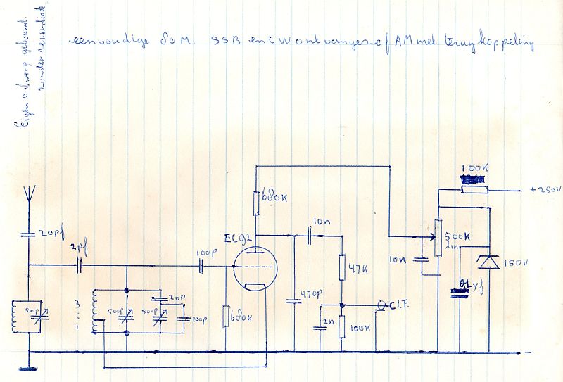
The regenerative receiver for Scheveningen radio and 80 meter.
The zenerdiode is drawn, but never mounted.
Tuning
Between the antenna and receiver an additional tuned circuit was added to suppress the audio breakthrough of strong broadcast stations just above 4 MHz and strong broadcast stations on the 2nd harmonic, the 7 MHz broadcast band. For the reception of SSB and CW, the receiver has to oscillate. And the second harmonic of the oscillator signal fell exactly in the 7 MHz band. After this addition, the reception was free of interferences. The antenna is connected with the top of this tuned circuit via a capacitor.
Then follows the tuned circuit. Via a very small capacitor, the first tuned circuit is connected to this tuned circuit. There are two tuning capacitors, one for the coarse tuning and one with a parallel and series capacitor for the fine tuning. Because of the parallel and series capacitors, the influence on the tuning of this second capacitor is much less.
Detector
After the tuned circuit you can find the triode. It detects the RF signals by means of grid detection, the grid-cathode space works as a diode. For the regeneration, the cathode is connected to a tap of the coil. The regeneration is controlled by lowering of the anode voltage by means of a potentiometer of 500k. It works excellent but it seems to me not really a good method. As not only the RF gain is reduced, but also the LF gain. And you want to keep the LF gain as high as possible!
The capacitor of 470pF at the anode is the decoupling of the RF signals to ground. The next capacitor of 10nF provides the separation of the DC voltage and AC signal. The resistor of 47k and the capacitor of 2nF are a low pass filter. And the resistor of 100k prevents that there is a DC voltage over the crystal phone.
Supply
A single phase rectifier and elco is used. It is not drawn. The planned voltage stabilizer by means of the zenerdiode of 150 volt is not used. The 100k resistor and 0.1uF capacitor are used. And of course, the 6.3 volt filament voltage from the transformer is connected to the tube and at one side to ground.
 The tube EC92 |
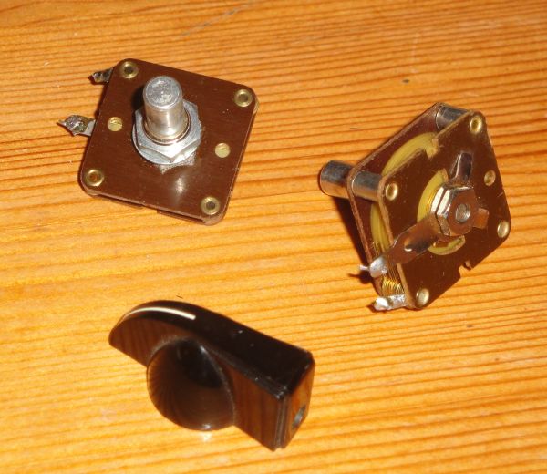
 Variable mica capacitors were used for the tuning. |
Crystal oscillator to tune the receiver.
Again barefoot to Amsterdam to buy crystals on the Waterlooplein market. One with a frequency of 2182kHz for the emergency and calling frequency for the shipping. And one with a frequency of 3640kHz to find the 80 meter band, the Oldtimer net. I made an oscillator, it did not need an antenna, as it radiated already enough. With a 9 volt battery, the connection clip was mede of an old 9 volt battery and was also the on- off switch.

The crystal oscillator used for tuning of the receiver.
Two frequencies, 2182 kHz for shipping and 3640 kHz for the amateurband (Oldtimer net).
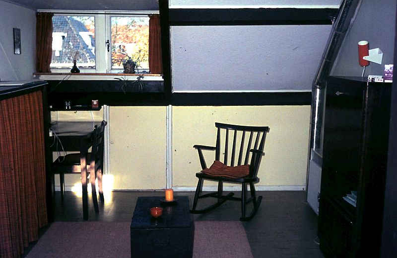
 My very nice student room! |
 With real kitchen! |

Later I did build a BFO in a real tube radio, left on the picture.

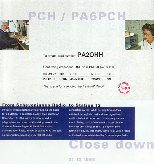
History!