Televisions and radio's with tubes.
0V0 MEDIUM WAVE RECEIVER
WITH A BATTERY TUBE
(1964)
KLIK HIER VOOR DE NEDERLANDSE VERSIE
Televisions and radio's with tubes.
 We played in unheated bedrooms. With ice on the windows as double glazing did not exist and only living rooms were heated! |
 And we had real winters with much snow and ice! |
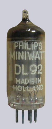
The applied tube DL92.
 The ATOM receiver was my first radio with tubes. It was a small 7 pin tube for use with batteries. The anode voltage was 13.5V (3 flat batteries in series) and the glow wire voltage came from a fat 1.5V battery. |

|
The tube radio "ATOM" from the book "Boys Radio" was built.
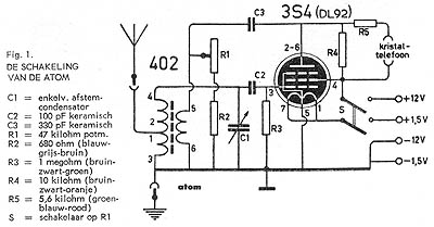
The ATOM receiver was my first tube radio. With a small 7 pin battery tube. It is a 0V0, so only a detector tube and no RF amplifier and no LF amplifier. The construction consisted of Amroh aluminum chassis parts. And the very well-known 402 coil was used, with which the whole medium wave could be received. For the tuning I used such a well known "brown" mica variable capacitor.
For an optimal match, the antenna is connected to a tap of the coil. The tube is connected to the top of the tuned circuit. Grid detection is used, the grid-cathode space acts as a detector. The grid can also receive a negative bias due to the grid current that always flows when the cathode-grid voltage is close to 0 volts. Here it is a little difficult because of the voltage that is caused by the filament voltage. Different parts of the cathode have different voltages.
The tube does not only amplify the detected low-frequency signal, but also the high-frequency signal. From the anode, a part of the amplified high-frequency signal is fed back to pin 5 and 6 of the coil 402. By means of the potentiometer R1, the part of the RF signal that flows via the coil or via the potentiometer can be adjusted. And that is how the regeneration control works. For amplitude modulation it has to be set to the level that it does just not generate. Via R5 (probably a blockade for the high-frequency signal), the detected low-frequency signal by the tube flows to the crystal phone.
Unfortunately, the adjustment of the regeneration was not really good. You could not set it to the level that it just started to generate, because the receiver began suddenly to oscillate. But it had still a good medium wave reception. Maybe I just needed to change the polarity of the filament, at that time, I did not have the idea to try that out.
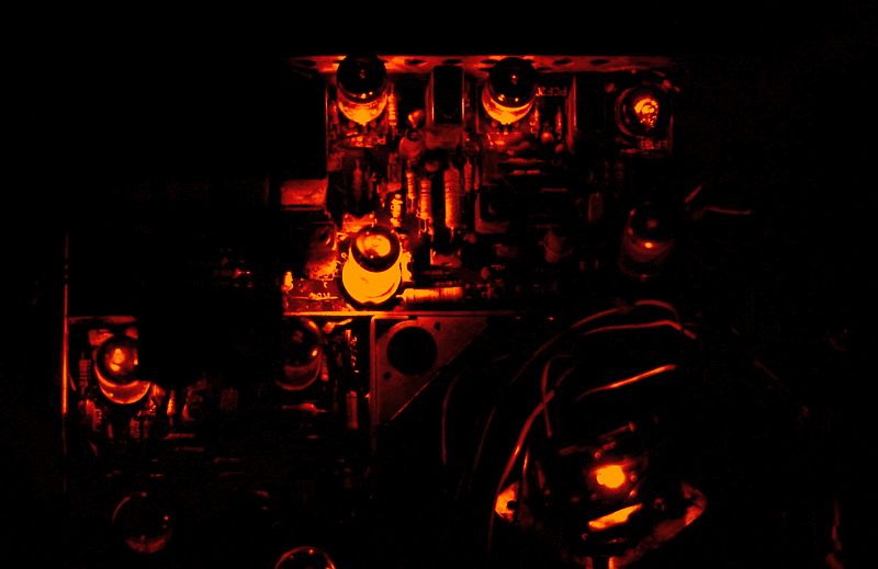
Early in the morning with my bare feet on the ice cold linoleum I was listening to the extended weather forecast and the prices of vegetables. Great when you hear that with your own receiver! With the curtain rail as an antenna and the bed as earth. And in the evening there were many foreign broadcast stations! That fading, wonderful!
Cold red toes, during many hours I was listening to all those medium wave transmitters. But that battery for the filament voltage, what was that quickly empty! A considerable drain on my pocket money! Unfortunately, I did not use this receiver very long. Accidentally I reversed the 1.5V battery and the 12V battery connections. A very short flash inside the tube and it was dead. I did not have money for a new one...
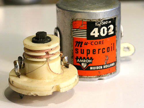 The famous Amroh mucore-402 coil wass used in this design. (Picture from the website of Piet Blaas) |
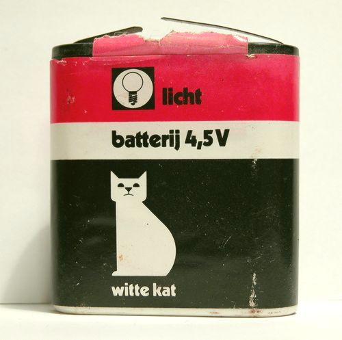 The anode voltage was 13.5V (3 flat batteries in series). |

Boys Radio!
I did read in this book during many hours!
The design of this receiver was found in this book.
Almost everybody had a radio with tubes.