Portable, barefoot in the snow with the small HIS transceiver, what a
difference compared with the equipment in the shack!
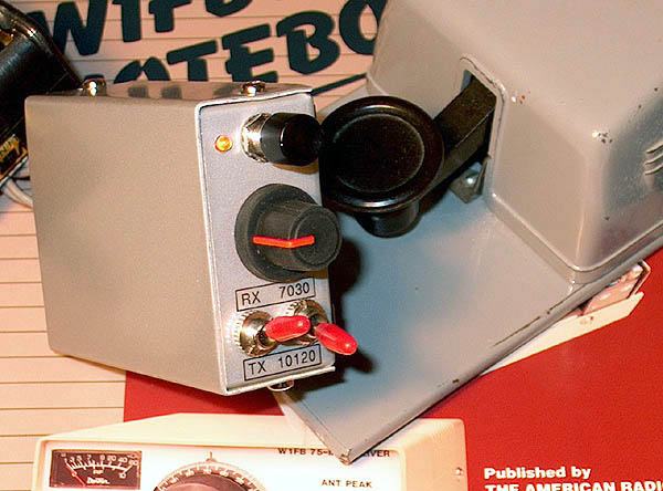
"HIS TRX" for the hiker!
A two band 1 chip + 1 transistor
1 watt QRP CW transceiver
(2000)
KLIK HIER VOOR DE NEDERLANDSE VERSIE
Portable, barefoot in the snow with the small HIS transceiver, what a
difference compared with the equipment in the shack!
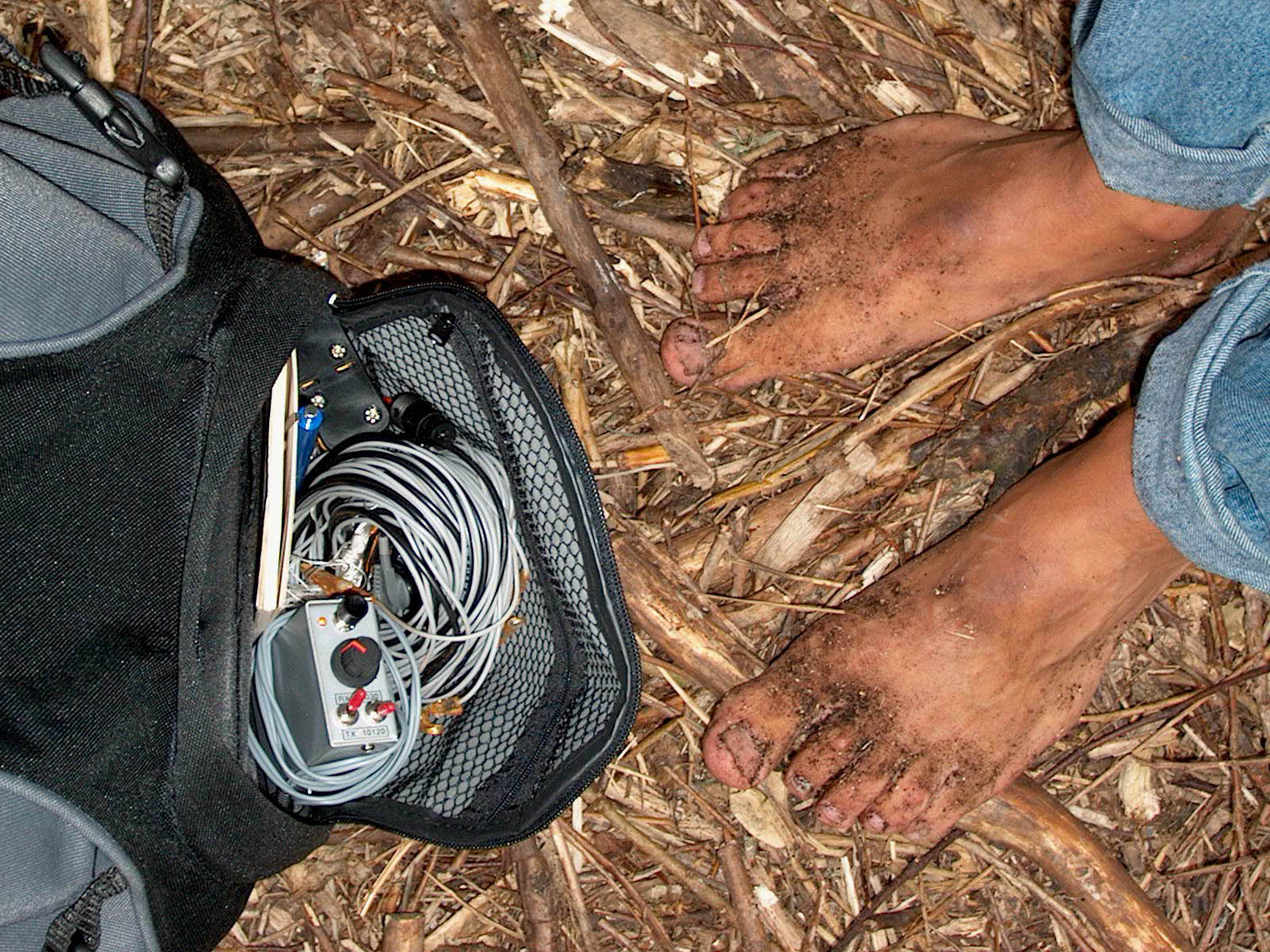
Back to Basics: portable on bare feet with the HIS transceiver!!
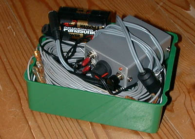
QRP station in a lunchbox!
Real simple barefoot technology....
Circuit diagram
LF amplifier
Just two "74HC4066 C-MOS switch transistor".
It looks as if the input resistor of the first stage is missing. But you can find it at the input of the mixer.
If LF oscillation occurs, decrease R1. Select R2 so that in receive mode, the supply voltage of the 74HC4066 is approximately 5 volts.
VXO
The VXO is a "C-MOS switch transistor". In transmit mode, extra RF power is needed for the final transistor amplifier. This is obtained by the circuit consisting of the diode 4148 and 330 ohm/100 pF. In transmit mode, the VXO is also tuned a bit lower in frequency due to this circuit. So when you receive a station, the VXO signal should be higher than it's frequency. Here the values of the tuning ranges of my version:
|
Crystal Frequency (kHz) |
Minimum Frequency (kHz) |
Maximum Frequency (kHz) |
| 7030.0 | 7029.5 | 7030.8 |
| 10120.0 | 10119.3 | 10121.2 |
Transmitter part
The VXO signal is amplified to 1 watt by a transistor 2N3553.
The 1k ohm resistor makes the amplifier more stable when mismatches occur. The 0.68 uH / 180 pF are tuned to the second harmonic of the 7 MHz transmit signal for extra suppression. One output filter is used for both 7 and 10 MHz.
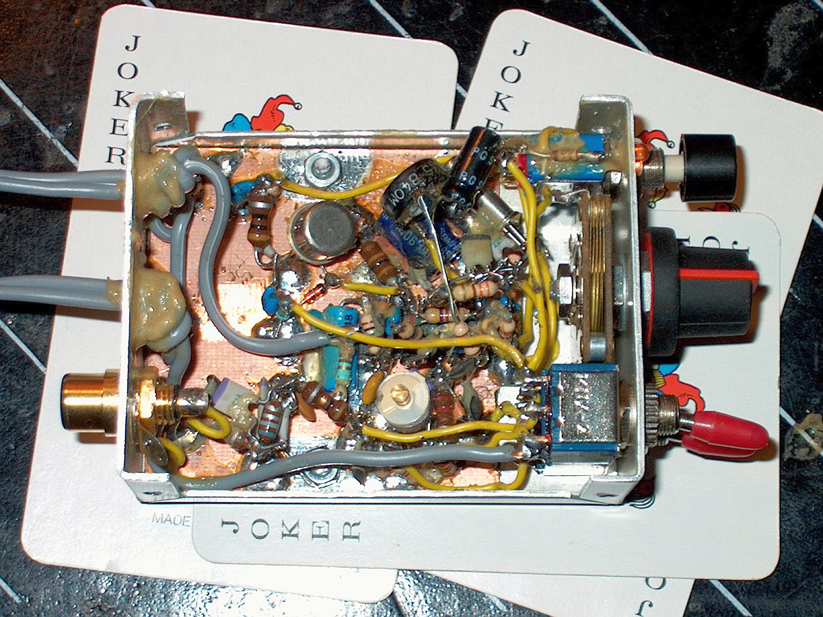
Notes
Built via the ugly method (dead bug method). Parts are soldered at one side of the print.
Inductances are commercially available types looking like big resistors.
Do not use a HCT type but a HC type!
If LF oscillation occurs, decrease R1.
Select the value of R2 so that in receive mode, the supply voltage of the 74HC4066 is approximately 5 volts.
The two earpieces of the headphone are connected in series instead of in parallel for more audio signal.
Options
Battery indicator (led off if battery low). The 2 band version is also given here as an option.
Performance
The receiver is quite good for large signal handling as needed for 40 m operation in the evening. Perfect QSO's have been made, also with a lot of QRP stations,
even long chats using inverted V dipole antenna's with the centre at 4 meters height.
Sensitivity: 3 uV signals are readable
3rd intercept: 8 dBm
Spurious responses: Better than -90 dB
RX current: 10 mA
Transmit power: 0.5 W at 8 V; 1.5 W at 12 V
Harmonic suppression: below 30 MHz: 43 dB, above 30 MHz: 55 dB
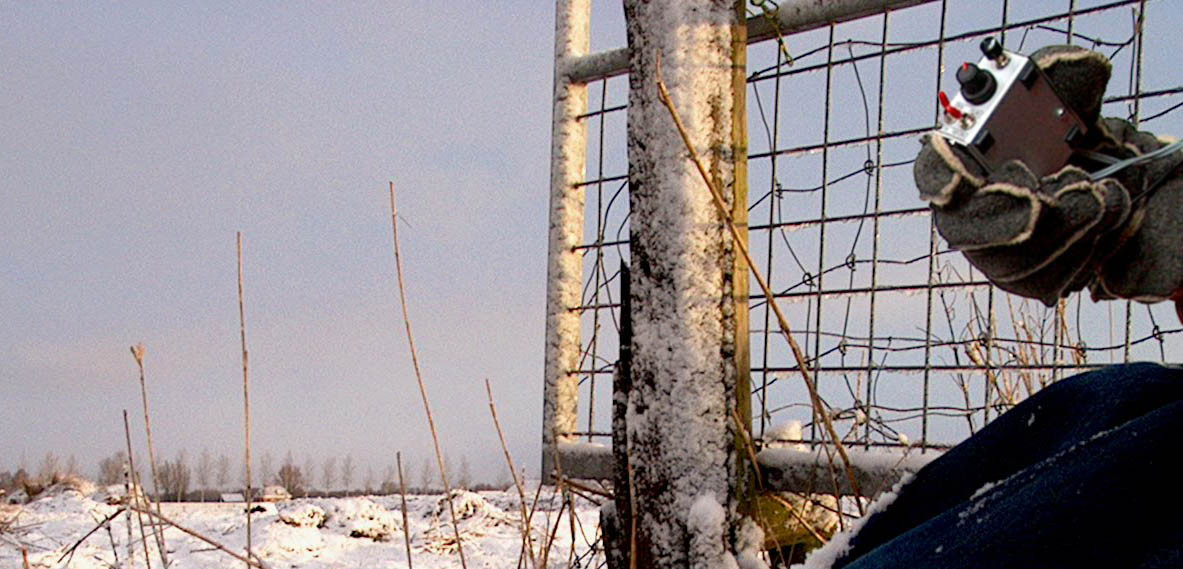
Back to Basics: portable on bare feet with extremely cold red toes with the HIS transceiver!!