
Barefoot Sailor! Long exciting barefoot walks with suffering way too cold toes
on the ice during the winter! And... Time to play with Navtex!!!
BAREFOOT NAVTEX RECEIVER BY...
THE BAREFOOT NAVTEX NERD!
(2023)
Never walk barefoot on the ice when it is colder than -3C to -4C because of the risk of frostbite on your toes!
Barefoot Sailor! Long exciting barefoot walks with suffering way too cold toes
on the ice during the winter! And... Time to play with Navtex!!!

Barefoot Navtex Nerd with suffering way too cold toes on the way too cold tiled floor to prevent static electricity!
Will a simple ferrite rod bring the simple solution that he needs for the simple Barefoot Navtex Receiver?
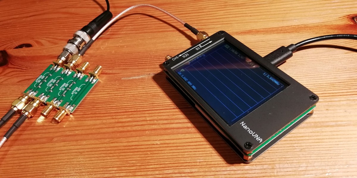
The famous nanoVNA and an attenuator to attenuate the HF output signal for receiver measurements.

A ferrite rod antenna is the simple solution!

Simple diagram!
Ferrite rod bandfilter (and antenna)
The ferrite rod antenna should not be placed close to metal objects and should also be kept away from sources of interference such as switching power supplies. So don't build the receiver in a metal box!!!
A coupling winding of 2 windings makes it possible to connect an external antenna. This coupling winding is completely isolated from the receiver. No conducted interference from the PC via the receiver can reach the antenna circuit! The ferrite antenna is tuned to the Navtex frequency of 518 kHz. For 490 kHz, an extra capacitance is connected in parallel by means of a switch. This is the only switch to change between the two Navtex frequencies! The capacitance for this ferrite rod is approximately 240 - 270 pF, but might be different for your ferrite rod.
The 10 nF capacitor creates a low-impedance tap for the HF transistor amplifier.
HF amplifier
One transistor is the HF amplifier, the gain is approximately 20 - 30 dB in combination with the ferrite rod bandfilter. Use a low-noise transistor like the BC550c or an older BC549c. The 470 ohm resistor with the 100 pF capacitor at the base of the transistor are a low-pass filter that suppresses signals from strong shortwave transmitters a little extra. The 1 nF capacitor with the 470 ohm resistor at the output are a high-pass filter that suppresses low frequency noise and signals (especially 10 and 18 kHz!) from the HF amplifier.
Mixer
The mixer is a BS170 FET. It is simple, it behaves like a switch that is switched on and off with a frequency of 500 kHz. It has a cut-off voltage of +3 volts or less and can be directly connected to the 74HC4060 oscillator with 5 volt TTL output. At the output there is a low pass filter of 2 capacitors of 10 nF and a resistor of 470 ohm. It suppresses frequencies above 18 kHz. What can I say more about such a simple mixer? Nothing!!!
Low Frequency amplifier
No op-amps, but ordinary transistors! The first transistor has a gain of (collector resistor / emittor resistor), that is 4700 / 47 = 100x or 40 dB. If you need less gain, increase the value of the 47 ohm resistor. The bias is obtained by a 1M resistor from the collector to the base. The exact collector voltage is not important, it is a low-level amplifier. The 1 nF capacitor at the collector is a low pass filter for extra attenuation of frequencies above 18 kHz.
The second transistor has a gain of 100k / 10k = 10x or 20 dB. Because of the feedback via the 100k resistor, it has a low-impedance output. Signals picked up by the LF output cable to the sound device are suppressed by this low impedance. The DC-collector voltage is approximately 0,7 x (100k + 47k) / 47k = 2,1 volt. Why not half the supply voltage? It is better suited for higher output levels in combination with low impedance loads. The 47pF and 1nF capacitor have a low pass filter function for extra attenuation of frequencies above 18 kHz.
The coupling capacitors of 1nF attenuate frequencies below 10 kHz so that the band pass of the LF amplifier is more or less limited between 10 kHz to 18 kHz.
500 kHz oscillator
A 8 MHz crystal and a 74HC(T)4060 oscillator-divider, very simple and reliable. If possible, take an HC type and not an HCT type. An HC type has a larger supply voltage range. Choose the value of Ra so that the supply voltage at pin A is 5 volt. For this version, Ra is 3900 ohm. But you can also buy small 500 kHz crystal oscillator blocks on the internet for a few euro's!
Low impedance eliminator, a very strange component!
The impedance of the receiver is very low at other frequencies than the reception frequency. And the coupling winding of the ferrite rod was shortened by the low impedance of the active antenna. It did not work as a good bandfilter anymore and the receiver was overloaded by strong AM broadcast stations. The mirror frequency was not suppressed anymore. Both problems were solved by the Low impedance eliminator resistor. It hardly affects the sensitivity of the receiver. When I connect the antenna, the noise increases, so the sensitivity is okay!
Various
In the power supply line you can find a 100 ohm resistor, 100uF and 0,1uF capacitors. They do suppress noise and interference of the supply voltages

The barefoot Navtex Nerd has terribly cold purple-red toes that have to suffer way too much on that ice cold floor of his workshop!
But he does not have problems anymore with static electricity and tries to continue with this exciting Navtex project!

The simple Barefoot Navtex Receiver, a simple construction! The barefoot Navtex Nerd was able to finish this project,
despite his terribly cold toes that had to suffer way too much on that ice cold floor of his workshop!
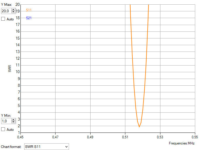
The ferrite rod antenna is tuned by means of a SWR measurement with the NanoVNA!
Here without the Low impedance eliminator resistor of 47 ohm to have a better dip.
Again!
Yes, the Barefoot Navtex Nerd did it again! A really simple circuit! The Barefoot Navtex receiver! Barefoot for weeks on the incredibly cold stone floor! Amazing, it was far too cold for his toes, yet his horribly cold toes barely survived! And then there is that exciting moment, finally the simple Barefoot Navtex receiver receives the Navtex messages

A Spartan-living, poor, barefoot sailor with an old boat and no Navtex!
Barefoot on ice with ice-cold toes and an old compass, a very simple life!
Line 21: LowerSideBand = False
Change Line 21 to: LowerSideBand = True
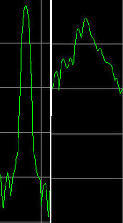
Use a good USB audio device! The peak at the left is a good one, the peak
at the right a cheap, low quality one. The good one is the Behringer UFO202.
ZIP file with NAVTEX reception results
Received Navtex stations 518 kHz near Valencia Spain with a PA0RDT miniwhip antenna during a few days:
Navarea 1 - North Atlantic, North Sea, Baltic Sea
E - Niton
G - Cullercoats
J - Gislovshammar
O - Portpatrick
P - Netherlands Coastguard
S - Pinneberg
T - V - Oostende
Navarea 2 - East Atlantic
D - Coruna
G - Tarifa
I - Las Palmas
R - Monsanto
Navarea 3 - Mediterranean Sea
H - Iraklio
K - Kerkyra
L - Limnos
O - Malta
P - Haifa
Q - Split
R - La Maddalena
T - Kelibia
U - Mondolfo
V - Sellia Marina
X - Cabo de la Nao

The miniwhip antenna and ice cold bare feet with suffering cold toes on that way to cold tiled floor!
The Barefoot Navtex Receiver project is a success!
Barefoot on the ice cold tiled floor of his workshop to prevent static electricity was really way too difficult and too dangerous for the vulnerable toes of the barefoot Navtex Nerd! His suffering toes barely survived the horrific cold! But... the suffering of his far too cold toes is rewarded with a huge success with that simple Barefoot Navtex Receiver and the miniwhip antenna! He's already looking forward to the next challenging Navtex project, barefoot again on that far too cold stone floor!