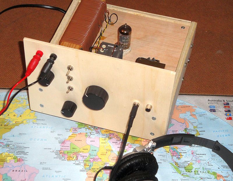
A 0V1 tube receiver for the shortwave band.
Regeneration, tuning, bandselection, volume control.
Even fine tuning by moving your had towards the coil.
A 0V1 TUBE RECEIVER
(2015)
KLIK HIER VOOR DE NEDERLANDSE VERSIE
A 0V1 tube receiver for the shortwave band.
Regeneration, tuning, bandselection, volume control.
Even fine tuning by moving your had towards the coil.
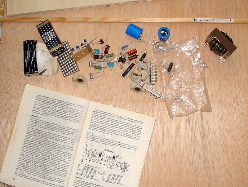
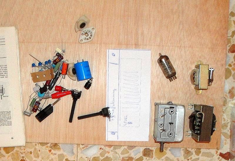
A nice present, all kinds of parts to make a 0V1 tube receiver!
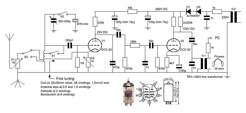
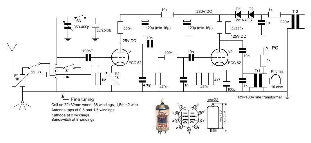
Diagram of the 0V1 tube receiver.
Fine tuning is done by moving your hand towards the coil!
big diagram
Tuning
At the input you can find the RF volume control P1 and the switch S2 with which you can select the most suitable connection at the coil, depending on the antenna and frequency band. By means of S1, a part of the coil can be shortened for the reception of higher frequencies.
And you can see a switch S3 with a crystal. Adjust the regeneration so that the receiver just oscillates. When you switch on S3, the receiver will lock to this crystal frequency when tuned close to its frequency. And then PSK31 stations around that frequency can be received.
Detector
After the coil you can find the first triode. It detects the RF signals by means of grid detection, the grid-cathode space works as a diode. For the regeneration, the cathode is connected to a tap of the coil. The feedback can be adjusted by means of potentiometer P2. When it is not possible to let the circuit oscillate over the whole frequency range, experiment with the correct tap of the cathode on the coil. Or lower the anode resistor of 220k to 100k.
The capacitor of 470pF at the anode is the decoupling of the RF signals to ground. The next capacitor of 10nF and resistor of 470k provide the separation of the DC voltage and AC signal and is also a high pass filter. The resistor of 100k and capacitor of 1nF are a low pass filter. And the next capacitor of 10nF and resistor of 470k are a second high pass filter and do have a second function. If the first capacitor of 10nF should have some leakage resistance, than this filter is an extra separation of the DC voltage and AC signal. So it is not a problem if the 10nf capacitors do have some leakage resistance.
Low frequency amplifier
Then the second triode follows, the low frequency amplifier. The cathode resistor with decoupling elco do provide the negative grid voltage. And via the 10nf capacitor, the amplified signal is connected with the LF transformer. As this capacitor does block DC, there is no high voltage on the LF transformer connections. So there are no dangerous voltages on top of the chassis!
The output transformer is a so called 100 volt line transformer that is used in audio systems in buildings. Connect your headphone to the 16 ohm connection and experiment with the best primary connection. Mine was the 0,5 watt connection.
Supply
TR2 is the transformer with a 220 volt output for the high voltage supply and 6,3 volt for the filament. This last winding is not drawn. The connections 4 and 5 are connected to ground and one side of the 6,3 volt winding, connection 9 with the other side of the winding.
The high voltage winding is connected to a resistor of 1k. The purpose is to reduce peak currents during the charging of the elco's and it is at the same time a kind of fuse. Together with the next capacitor of 1 nF, it is also a low pass filter to suppress transients and high frequency signals. The capacitor also prevens RF hum caused by the rectifier when switching from the non-conducting to conducting state.
The rectifier consists of 2 diodes 1N4007 in series, so that there is some reserve for high peak voltages. Then you can find both elco's of 120 uF, to filter the ripple from the DC voltage. The value is quite high, the minimum value is approximately 15 uF. The supply of the detector trap has an extra filter by the second elco and the 10k resistor.
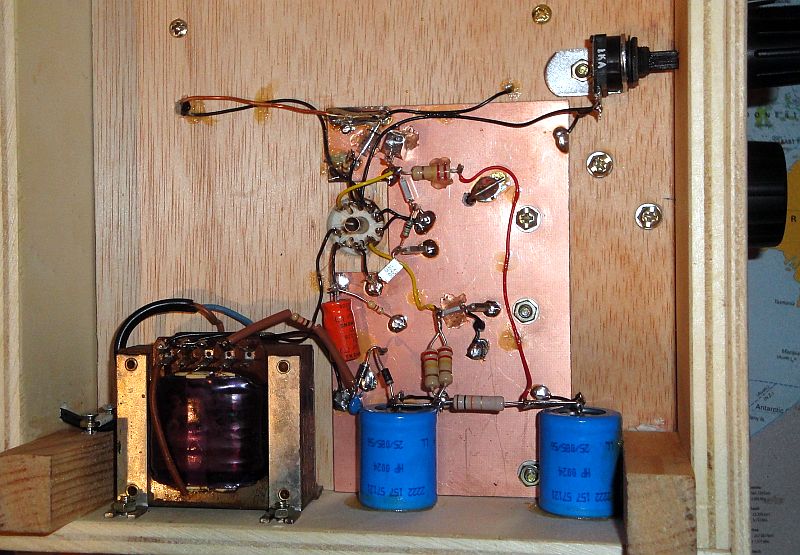
Big high voltage parts and big resistors!
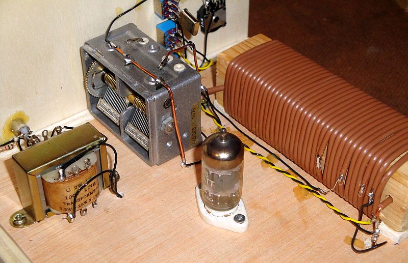
Tube, LF transformer and coil.
Fine tuning is done by moving your hand towards the coil!
| Tuning (degrees) | Band 1 (kHz) | Band 2 (kHz) |
| 0 | 1700 | 4650 |
| 90 | 1950 | 5300 |
| 180 | 2400 | 6500 |
| 270 | 3100 | 8300 |
| 360 | 4000 | 10500 |
| 450 (360+90) | 5200 | 13200 |
| 540 (360+180) | 6450 | 16150 |
| - | - | - |
| 60 | 1850 | - |
| 315 | 3560 | - |
| 210 | - | 7030 |
| 350 | - | 10140 |
| 470 (360+110) | - | 14060 |
Results
Unfortunately, the antenna and reception here is not so good as at my old location. But it was nice to listen again to all those shortwave broadcast stations and also CW signals could be received on various amateur bands. Here below some recordings of received signals:
CW signals
Broadcast
Broadcast
Remarks
Instead of the ECC82, also a tube ECC81 can be used, it works a little better.
A problem with the receiver is the direct coupling of the tuned circuit of the oscillating detector with the antenna. Oscillator signal is radiated via the antenna and can cause interference in the reception of other receivers. Also hum can be caused in the receiver. Many switched power supplies have rectifiers that can be considered as switches, switching on-off with the mains frequency. As the mains is connected to the antenna system via the transformer capacitor, the oscillator signal is AM modulated a little. This can cause much hum. Also the oscillating frequency can change a little in the rhythm of the mains frequency. Then the oscillator frequency is not fully stable and CW signals may sound a little rough. A solution is a 1V1, a receiver with a RF stage. The RF stage is the buffer between the oscillating detector and antenna. It suppresses the oscillator signal to the antenna and the load of the oscillator remains constant
An alternative solution is the use of an active antenna. The built-in amplifier is then the buffer between antenna and receiver.
How shall we make it? First we have to think and to make some drawings.
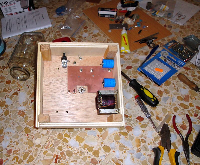
Under construction!