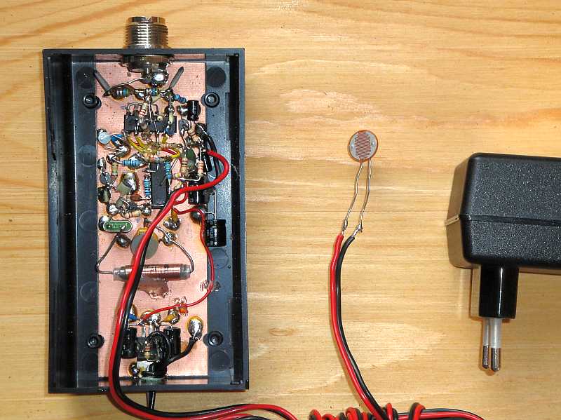
The beacon transmitter of 10 milliwatt with Light Dependend Resistor (LDR).
The beacon transmitter is keyed by the LDR.
10 MILLIWATT QRSS BEACON TRANSMITTER FOR
30 METER KEYED BY A WEBBROWSER
(2010)
KLIK HIER VOOR DE NEDERLANDSE VERSIE
The beacon transmitter of 10 milliwatt with Light Dependend Resistor (LDR).
The beacon transmitter is keyed by the LDR.
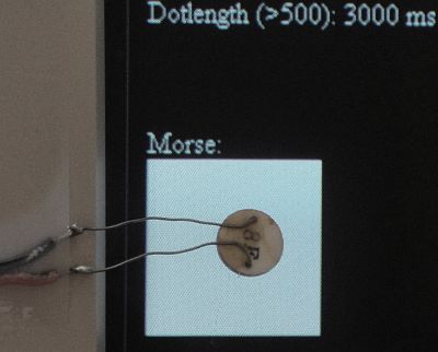
The LDR is placed in front of the monitor screen. The white square
on the screen blinks on/off in the rhythm of the morsecode.
This is done by a HTML program running in a webbrowser.
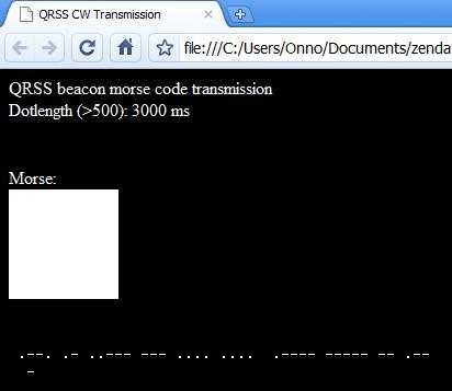
The HTML program running in a webbrowser, here Google Chrome.
The white square blinks on/off in the rhythm of the morsecode.
Click here to see the HTML program running, that will make clear to you how it works.
Click here to download the zipped version of the HTML program.
Click here to download a zipped version that transmits in time synchronized 10 minute intervals.
You can modify the program by means of an ASCII text editor like Notepad. In one of the first lines after "Data", you have to fill in the desired morsecode. And after dottime the keying speed in milliseconds (normally 3000 ms for a dot). By means of style sheets, two squares are defined, a white square and a black square. And by means of a timer interrupt routine named "function NewTime()" and the function "innerHTML" for modification of a part of the screen, everything is controlled. After that the morsecode is transmitted, the HTML program is loaded again and run by the webbrowser. During a transmission, it is possible to modify the HTML program. I can do that from any location, as together with the webbrowser, a FTP program is also running on the PC. But there are other possibilities for that. And on the PC, also the program ARGO with simple receiver is running, so that I can see from a remote location if everything is going well.
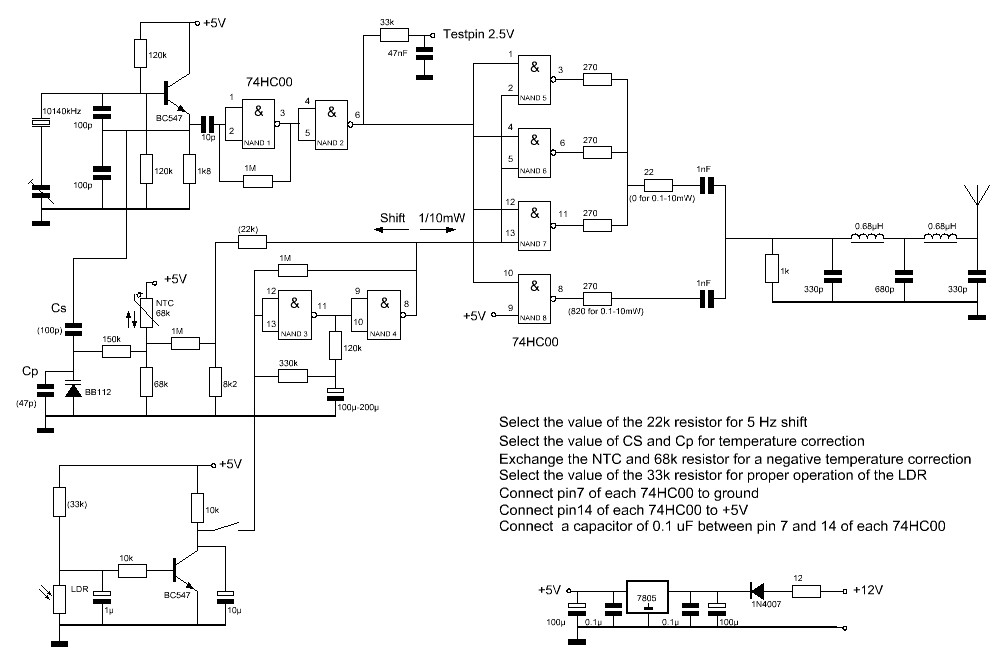
Circuit diagram
big diagram
Temperature stabilization
The frequency has to be very stable. It is quite difficult to adjust the beacon transmitter on a frequency of 10140.0 tot 10140.1 kHz and to avoid drift due to temperature changes. A temperature correction circuit was made with a NTC resistor and a varicap. The drift could be reduced considerably. For a positive frequency drift correction, you have to connect the NTC in accordance with the diagram. For a negative correction, the NTC resistor and 68k resistor have to be exchanged. Of course you can also take a NTC resistor with a different value. Exchange the 68k resistor then for one with the same value as the NTC. Increasing of Cs and reducing Cp increases the correction, reduction of Cs and and increasing of Cp does reduce the correction. Finding the correct value is done by of trying out various values of Cs and Cp while cooling down and warming up the transmitter.
The Light Dependent Resistor (LDR)
It is important to keep a distance of at least 0.5 cm between the screen and the LDR. Otherwise, the high voltage of the screen can disturb the LDR. The flickering of the screen has also to be filtered out. And you have to avoid interference from daylight by screening the LDR and screen with a piece of cardboard or so. By using a LDR we have a full galvanic isolation between the PC and the 10 milliwatt beacon transmitter! Of course you can modify the program so that you have a second square with second LDR to switch other things like power or switching between transmission and reception.
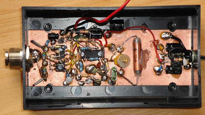
The circuit mounted in a plastic housing on an unetched piece of PCB.
An extra coil in series with the crystal was necessary to tune to the correct frequency.
Results
It is a strange experiment. The 10 milliwatt transmitter is switched on and... The needle of the power meter does not move! And it is even a QRP power meter! But how do you get reception reports? Quite soon I received an e-mail with screenshot from Dusan, YT1DL. Dusan many thanks, with this report the experiment was already 100% successfull! Not only the high shift with dots and dashes with 10 milliwatt was visible, also the lower shift with pauses between the dots and dashes of 1 milliwatt was visible! Dusan does not use the program ARGO but Spectran.
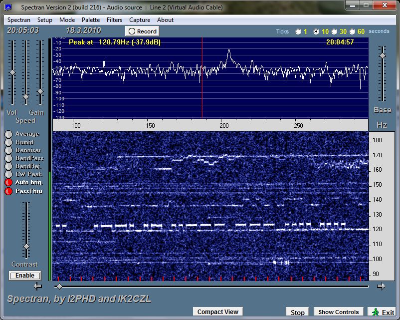
Reception report from Dusan YT1DL, received by e-mail.
Not only the 10 mW, but also the 1 mW shift (pauses, 4-5 Hz lower) is visible.

Reception report of the QRSS grabber of G4CWX in Bristol.
Also here the 1 mW shift (pauses, 4-5 Hz lower) is visible.

Reception report of the QRSS grabber of I2NDT in Bergamo.
Also here the 1 mW shift (pauses, 4-5 Hz lower) is visible.