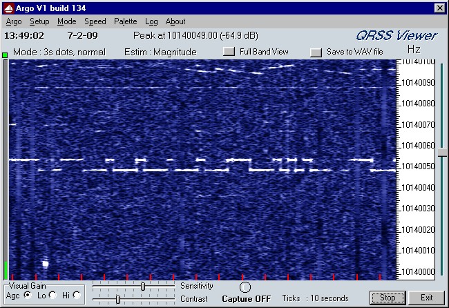
I0/N2CQR, a 20 milliwatt beacon in Rome!
Absolutely inaudible, but perfectly visible!
SIMPLE 30 METER RECEIVER FOR
LOW POWER QRSS BEACONS AND PSK31
(2009)
KLIK HIER VOOR DE NEDERLANDSE VERSIE
I0/N2CQR, a 20 milliwatt beacon in Rome!
Absolutely inaudible, but perfectly visible!
The simple receiver for 30 meters QRSS beacons and PSK31. I wanted to
receive the 10 milliwatt beacon transmitter with it during my holidays!
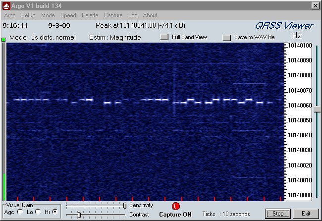
The 10 mW beacon signal, 8 s high, 6 s low with a shift of 4 Hz.
It could be received at a distance of 1650 km!
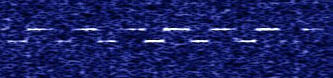
Here a recording during 8 minutes with a smaller bandwidth.
Absolutely inaudible, but those 10 milliwatts were often visible!
Our old receivers are completely unsuitable for QRSS reception
due to insufficient frequency accuracy and stability.
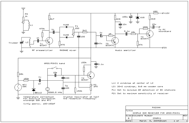
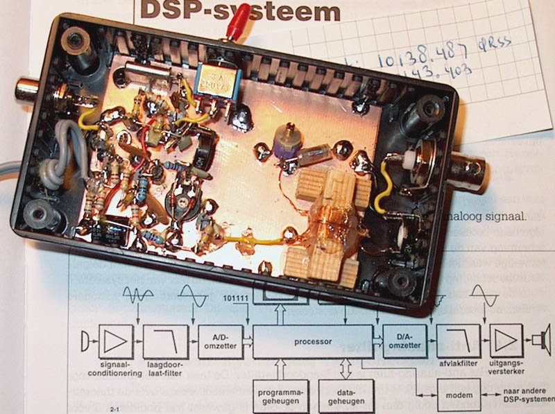
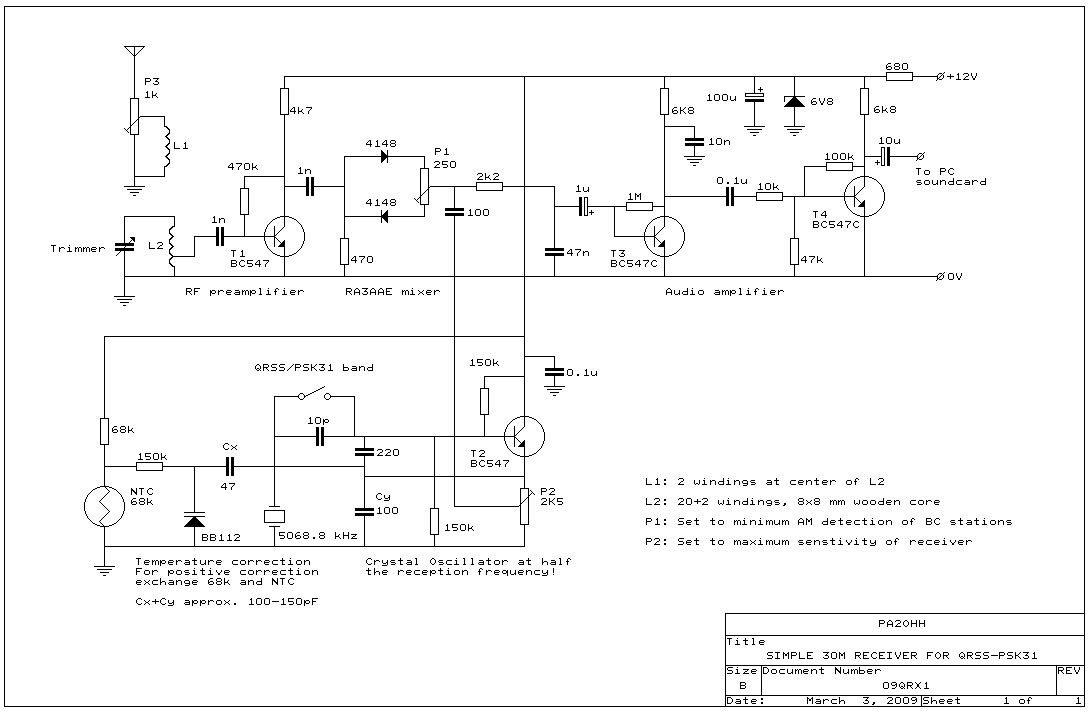
Circuit diagram
big diagram
RA3AAE mixer
One of the diodes conducts during the positive half period of the sine of the crystal oscillator, the other diode during the negative half period of the sine. But due to the voltage drop of approximately 0.7 V, the diodes will only conduct during the positive top and the negative top of the sine and not near the zero crossings of the sine wave of the crystal oscillator. So they do behave like a switch that switches 2x on/off during one sine period. That is why the crystal oscillator has to work on half the reception frequency! And that is the frequency of the cheap, easily obtainable 5068.8 kHz crystal. The level of the oscillator is very important and can be adjusted with P2 by ear.
With P1 and a correct adjustment of it by ear, the sensitivity for strong AM signals can be reduced considerably.
VXO
The crystal oscillator works on 5068.8 kHz, just beside half the reception frequency. The exact value is not important, it is measured during the calibration and corrected in the software. You can receive the QRSS becons between 10140.0 - 10140.1 kHz. The frequency of the crystal oscillator should be so, that the beacon band is somewhere within the audio range of 1 to 2 kHz. By means of a serial capacitor, the frequency can be increased so that you also can receive PSK31 stations above 10142 kHz.
Temperature stabilisation
Between 10 C and 30 C, the frequency drift was approximately 20 Hz. Already much better than the 70 Hz of the beacon transmitter. It seems indeed that 5 MHz crystals are more temperature stable. Often an oven is used to stabilize the temperature of the crystal. That was not possible here because of the high supply current of an oven. I wanted to use batteries to supply the receiver. But with a NTC resistor and a varicap a temperature correction was made and the drift reduced to less than 5 Hz between 10 C and 30 C. For an upwards frequency correction, the NTC has to be connected as in the diagram. For a downwards correction, exchange the NTC and 68k resistor. Of course you can also take a NTC resistor with another value. Exchange the 68k resistor then for a resistor with the same value as the NTC. Increasing Cx and reducing Cy increases the correction, reducing Cx and increasing Cy reduces the correction. Finding the correct value is a question of trying out while cooling down and warming up the receiver with various values of Cx and Cy.
Low frequency amplifier
One transistor was not enough for the weak QRSS signals. That is why an extra transistor T4 was added. The output is low impedant due to the strong feedback via the 10k / 100k resistive divider from the collector. A cable that is connected to a low impedant source is less sensitive for interferences. And by adding extra gain, the level on the connection cable with the soundcard is increased and because of that even less sensitive for interferences (hum etc.). Therefore, it is possible to use a long, unscreened flat thin loudspeaker cable for the connection between the receiver and the soundcard input of the PC. So it is not necessary to place the PC close to the receiver and the flat cable fits easily under a door.
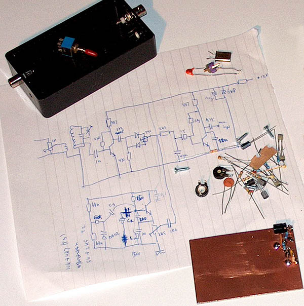
The circuit is mounted in a plastic housing on an unetched piece of PCB.
Software
On the internet you can find various suitable software programs. Just search for QRSS and you will find all kinds of software and many very interesting information. I use ARGO of Alberto, I2PHD and Vittorio, IK2CZL. For uploading of the ARGO screencaptures I use Argo Upload by Rik Strobbe (ON7YD). Then it is possible to see via internet what the receiver at home does receive at that moment.
Calibration
For the program ARGO, two calibrations have to be done. Firstly the accuracy of the soundcard. You can do that by touching the input of the soundcard with your finger and to measure the 11th harmonic of the mains (550 Hz or 660 Hz if the mains frequency in your country is 60 Hz). My soundcard had a deviation of 11 Hz! Or the "measured frequency" was 550 Hz and the "displayed frequency" was 561 Hz. However, the laptop had a deviation of 0 Hz!
After the calibration of the soundcard, the local oscillator frequency has to be entered in the ARGO program. You cannot measure it, connection of a frequency counter will cause a shift in the crystal oscillator frequency. So connect a signal with a known frequency (for example 10140 kHz) to the receiver and adjust the offset value in the ARGO program so that it displays the correct frequency. I do use a frequency counter with simple frequency standard to measure the frequency of the known signal. For my receiver, the offset is 10138487 Hz, so the crystal oscillator frequency is 5069.243 kHz. And the QRSS beacon band of 10140.0 to 10140.1 kHz is in the audio range 1513 to 1613 Hz.
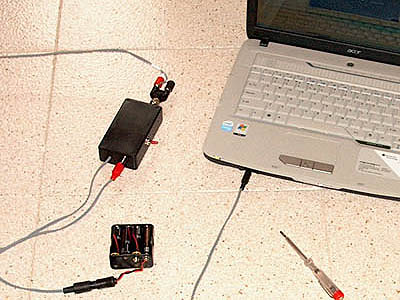 The complete station: receiver, batteries, laptop and a screwdriver to adjust the RF attenuator. |
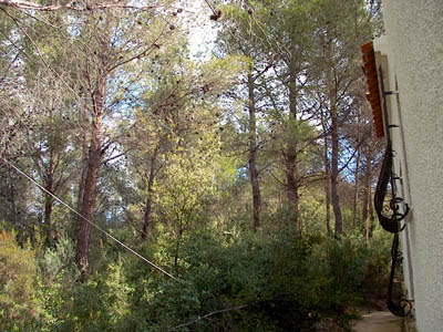 The antenna was at a height of 2 to 3 meters behind the house in the trees. The flat, thin antenna cable fitted through a small hole near a window. |
Description of the mobile reception station
The receiver, the antenna and the connection cable with the PC and the batteries were all stored in the laptop bag. The antenna was made from a piece of flat thin loudspeaker cable of 15 meters. The final 5 meters was split into a dipole antenna of 2x5 meters. The remaining 10 meters is the antenna cable to the receiver. The outer ends are mounted in a banana-BNC coupling adaptor. The flat thin cable fits easily through a hole, that is often a problem with coax and a coax plug.
The cable between the receiver and laptop is 8 meters long, it is the same flat cable as is used for the antenna That is quite long. But then it is possible to place the receiver in a bedroom and the laptop in the kitchen or living room. It was very important to use the internal accu of the laptop. Reception of QRSS signals was not possible when the charger was used due to its radio interference.
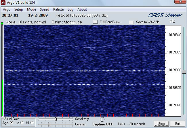
EA1FAQ with 10 milliwatts, received in The Netherlands. From Spain to The Netherands is also possible!
Dashes are a dot with a high shift, a "dot" is a dot with a low shift.