Amateur Conversion for the FM1000 PMR
PA1MT
Converting
the Philips FM1000 PMR to 70cm's / FM1100 to 2m
Provided you can get hold of the right versions, the Philips/Simoco FM1100 and FM1200 PMRs (Private Mobile Radios) are probably the easiest converted ex-PMRs for amateur use. In the FM1100 no conversion is required except changing two EPROM's and one EEPROM, while in the FM1200 the extra work consists of relocating 1 (yes, one) small PCB track. What's more, these beautifully designed radios require no alignment whatsoever. Thanks to their compact and robust construction, LCD readout and lush transmit power levels of up to 25 watts, both radios are highly suitable for mobile use.
About the FM1200
In all likelihood, any Philips/Simoco PMR Type FM1200 STM22 found on rallies, car boot sales etc. was at some time part of a large trunking radio network operating in the UHF band. The FM1200 was originally designed around 1990. This once very advanced, very expensive microprocessor controlled FFSK transceiver consists in essence of three modules:
1. Control Board, holding two micro controllers (type 80C31) with RAM, EPROM, etc. plus an amount of digital electronics. The lot is in charge of nearly all control systems in the radio. The trunking section on this board has no value for radio amateurs. The control board may be found under the smaller cover.
2. Analogue Board, containing all analogue electronics, the PLL, VCO, RF, IF and audio amplifiers, etc. For convenience's sake, we also count the transmitter PA in this section. Remarkably, the entire transmitter and receiver are completely adjustment-free between the specified band limits of 400 and 440 MHz (TM band). So, readjustment is never necessary after any frequency change between these band limits, as the receiver and transmitter are automatically kept tuned to maximum sensitivity and output power respectively. This system is called Auto RF Tracking and is implemented by two dozen varicaps tuned by D-A converters, all under control of the 80C31. The analogue board greets you if you open the larger cover and remove the internal screening plate.
3. Console, this is the user control part with the LCD. The console contains its own micro controller system, again built around an 80C31. So far I came across 3 different types of console: 'simple', 'basic' and 'keypad'. For this conversion it is assumed that a radio with a keypad console is available.
The three modules that make up the radio communicate via an internal bus en simple pin headers and sockets. The original EPROM's contain about 32 or 64 Kbytes of machine code for the 80C31s. Years ago, at the Simoco headquarters in Cambridge, the FM1200 was jokingly called ‘a computer acting as a radio’. The version STM22 supplies 25 watts of RF power, is suitable for the 12.5kHz raster, and covers 400-440MHz. In other words, it should be ideal for radio amateur use.
The radios in the FM1000 series are easily assembled for local control (i.e., with the console mounted on to the radio) or for remote control (console mounted on the dashboard and radio somewhere else in the car).
The conversion described here was developed by Gerrit Speelman PA1MT. The conversion typically takes less than 15 minutes to complete. All the designing, debugging and head scratching has been done for you and comes in the form of this article and three ICs: two EPROM's and one EEPROM. As far as transmit power levels are concerned, the FM1200 puts competing radios like the SE Condor 46 and some other ex-car phones to shame. In practice, 25 watts of RF is a comfortable level to have available on 70cms, providing much more ‘push’ than a 6 or 10 watts rig, especially when going mobile.
The conversion consists of three steps, or, if your like, 'phases'. To begin with, new software is fitted in the console (EPROM). Next up is the only bit of solder work you'll have to do: relocating a single PCB track. This effectively puts the internal trunking processor to sleep, enabling the FM1200 to behave like a regular NBFM transceiver. Next, we fit a new ‘firmware’ EPROM in the radio itself. Finally, a suitably reprogrammed EEPROM is fitted. This is an 8-pin IC containing about 1,000 user settings. Once you've managed to get your very own FM1200 STM22 on the worktable, I'd say start the conversion job with… obtaining a conversion kit!
Warning:
The Simple
Conversion is not suitable for FM1200
radios with a Type-1 control board. This includes the ex
Electricity Systems VHF FM1200 SB014 which is around in
vast quantities in the UK.
and also for FM1200 radios with a Standard console .
This includes the German "Bündelfunk / CHEKKER
FM1200 STM23" whit
!!!
Information for convertion from this trunking
PMR is available at http://www.dl1ydd.de .
General tips
Converting the console
Converting the radio proper

Testing
Use heavy-duty (min. 2.5mm2 csa) wire for the supply cable, and insert an in-line slow-blow fuse rated at 10A. Connect the microphone, power supply and loudspeaker. If your set came without a connector/cable set, look at Figure 2 to find out the pin out of the supply/LSP connector on the rear of the radio (rear view of connector). Pin 8 (Ignition) is usually permanently connected to the positive wire (+12 V).
Figure 2. Pin out of the combined supply/loudspeaker connector on the rear of the radio. If you can't get hold of an original mating socket, buy discrete Mate 'n Lock pins to make one yourself.
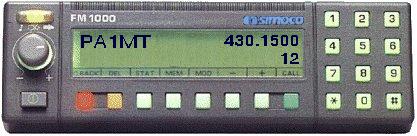
Set the supply to about 13 volts and switch on the radio using the pushbutton on the front panel. Sometimes the radio produces a short 400Hz tone. The display will indicate the loudspeaker symbol in the top left-hand corner. To the right, you will see the start-up frequency and below it the associated channel number. Current consumption at this point should be less than 600mA with the LCD backlight turned on. If you get ‘Undefined Error Code 03’ then the radio will contain no or incorrect user data in the EEPROM. Contact me to discuss EEPROM replacement.
First connect a dummy-load and then key the transmitter. RF power should be in excess of 25 watts (I measured 28 watts on a Bird Thru line, and 26 watts on a Marconi TH1035).
Additional information
The program and data in the EPROM installed on the control board originate from the FM1100, the 'non-trunking' sibling of the FM1200. The program and data in the console EPROM were developed out of an example taken from an FM1100. Mind you, the frequencies and texts that appear on the LCD are held in the console EPROM, not (unfortunately) in the EEPROM!
All radios from the FM1000 series look identical and are, in principle, produced for any PMR band between 50MHz and 550MHz. So be sure to read and understand the type number! The -STM22 is a hit for 70cm amateur use. When purchasing an unknown ‘FM1000’ radio, make sure you are aware of the number/letter combination indicating the frequency band, bandwidth and transmitter power. The FM1200 SK111 seems to be around in vast quantities (ex trunking systems in Band 3) but it frequency range is (K1 band = 174 to 208MHz).
A K1 band FM1000 will work ok down to about 156 MHz just by only adjusting the VCO; so it could be a PMR or Marine set. TX power will be about 20W at 156MHz. If you add small value capacitors (a few pF) across the VCO tuned circuit you can get the synth to lock at 145MHz. If you add the same value capacitors across the Receiver module tuned circuits (underneath the module) you can get good rx sensitivity. TX power will be about 20W at 145MHz. If the K1 FM1000 has a Keypad console, change the EPROM to make it an FM1100 console. If it has a numeric console this can't easily be changed to FM1100; you would need a new console.
modification for FM1200 radios with a Type-1 control board.
This includes the ex Electricity Systems VHF FM1200 SB014 which is around in vast quantities in the UK.
Mk1 control board it has red and Yellow lines on it, the yellow are cuts in the print, the red is a link from end to end. There are 4 cuts and 5 links The mod consists of 1 making the cuts and links 2 fitting a standard 1100 27c512 firmware prom into the holder, spare pins at top. 3 Fit a standard 1100 prom in the keypad head and check to see that the 1100 link is made next to it. 4 Zero the eeprom using a CDP 5 Downloading a suitable 2mtr .con file to the radio using CDP The Mk1 board will now act as a Standard 1100 but as the simple conversion it will not have ctcss or tones.. Whit special thanks to Ron Ayling G3YUH for this modification;

This excellent board photo is from Dave G7UZN
EQUIPMENT
VARIATIONS

|
02 France
03 West
Germany
04 USA
06 Denmark
07 Sweden
09 Canada
10 Norway
11 Switzerland
12 Finland
13 Holland
14 Italy
18 Spain
25 Austria
27 Belgium
30 Hong
Kong
31 Portugal
IF Indonesia
SL Stockholm
Buses
1
Analogue Transceiver Type
FM1100
2 FFSK Transceiver Type
FM1200
3 FFSK Transceiver Type
FM 1300
Equipment Labeling
2
Philips Label (Grey Transceiver)
Equipment Color
2
Grey
Software
0 Less Software
(EPROM &
EEPROM)
2 1-4
Digit Console, Enhanced EEPROM
3 Basic
console standard EEPROM
4 Keypad
Console, Enhanced EEPROM
5 6 Digit
Console, Enhanced EEPROM
Environmental Protection
Z Standard
Production
1 iP54 Production
Frame Type
1
Standard Frame
2 Extended Frame
(Required for Keypad Console
and/or Modem Interface)
S 12,5kHz
R 20kHz
V 25kHz
Frequencies
EO 68-
88 MHz
BO 132-156
MHz
A9 146-174
MHz
Ki
174-208 MHz
K2 192-225
MHz
K8 225-235
MHz
K9 225-235 MHz
TD 380-440 MHz
TM 400-440 MHz
TZ 410-430 MHz
T4 425-450 MHz
UO 440-470 MHz
Wi 470-500 MHz
W4 500-520 MHz
1 ±5ppm
2 ±2ppm
1
Standard VHF (1-25/30W)
2 Standard
UHF (6-25W)
3 Low
Power UHF (1-6W)
1 CTCSS
+ Sequential Tone signaling
2 Sequential
Tone signaling only
3 CTCSS only
4 Less
signaling
5 CTCSS + Sequential Tone Signaling (Less
Reverse Tone Burst)
6 CTCSS
(Less Reverse Tone Burst)
The transparent film you will have found on the LCD is, of course, intended for the original application of the radio. Using the original film, a graphics program, a laser printer and some transparent sheet it is easy to make a new film with the appropriate legends on it. An ordinary copy machine is also suitable, although professionals will of course have nothing less than real acetate film. If you do not have the equipment or wherewithal to make the film yourself. Loading a different set of frequencies is only possible if you have rather special equipment available capable of directly writing into the EEPROM using a prescribed format. This equipment is called PDP (Portable Data Programmer) or CDP (Computer Data Programmer). As part of my collection FM1000
Unfortunately the FM1200 does not have an internal 1750Hz call tone generator, 5-tone calling or CTCSS, so that you have to add these options your self using suitable hardware. Fortunately, the microphone has enough space to allow a miniature 1750Hz tone call board to be fitted.
Microphone connector pin outs


FM1000 the series
| Top-of-the-range PMR keypad control head whit the capability of 48 alphanumeric characters. |
|
| Standard FM1100 control head whit 100 channel capability. Six-digit liquid crystal display. Software coded function buttons. |
 |
| Standard FM1200/1300 control head for trunking systems providing short from dialing and in-fleet calls. Software coded function buttons This one is not suitable for conversion !!" |
 |
| Basic FM1000 control head. Operates up to seven PMR channels or preprogrammed signaling functions. Individual Led indicators for every function button. |
 |
The
Accessories

![]()

Technical Specifications

Using
a FM1000 for
9600 Baud packet and Pocsag receiver
General:
Use of 9600 requires a 25 kHz bandwidth transceiver. Ensure that
the 455 kHz black ceramic filter is type 'D'.
Ensure that the bandwidth dependant resistors are correctly
fitted as follows:- R56 is 1.8 kohms; R216 is 22 kohms; both
R61 and R62 are 18 kohms. All four resistors are leaded. Ensure
that the 21.4 MHz metal canned crystal filter is
either Toyocom type '21J3B' or NDK type '21M15CH' (the 15
indicates the nose bandwidth) .The top of the letters on the
filter should be nearest to the synthesiser can. If the Toyocom
filter is marked with a red dot this goes towards the front of
the board.
Transmit:
Inject signal at junction of C75 and R58, both close to IC53
(3403).
Fit R58 as 47 kohms smd resistor. R58 is not normally fitted on
the standard factory build standard.
Receive:
Obtain signal from pin 1 of IC203 (3403), or from pin 8 of IC204
(4066).
This signal is also available at PLJ. Remove SKH from PLH near to
the audio amplifier TDA2002. Plug SKH into PLJ nearby. Receive
audio will now be available on the speaker pins of the power
socket.
PTT:
PTT is available at pin 9 of SKTC on the Control board. SKTC is
the flexi-strip connector at front left of the board. pin 9 is
not
easily accessible here. Instead connect to R326 (1 kohm) on the
side away from IC303.
Hartmut DL1YDD write to me this information for a POCSAG
receiver :
For a suitable tap point. I started with the 9k6 packet radio infobut
that did work only very bad.
Looking into the schematic showed that this tap point is not good
because the signal is already filtered
and is also after the squelch isolation switch.
Much better (for POCSAG which has similar requirements than 9600 baud
packet radio) is the junction
between R225 and R223. That is exactly where the original FFSK signal
is taken from.
Voltage level is suitable, you can also close squelch and still
have signal at this point.
CUSTOMIZATION of
FM1100/FM1200 KEYPAD CONSOLE MESSAGES
Use of 27C512:
The Keypad Console code is normally supplied in a 27C512
Eprom even though a 27C256 eprom could be used. The code is
normally blown into both halves to avoid failures caused by
selecting the wrong half of the eprom. So the code lies in the
range 0000 to 7FFF, and is repeated from 8000 to FFFF. The
following text will refer to the lower eprom half, with the upper
half figures given afterwards in brackets. The standard
Alphanumeric Keypad Console will be linked to use the
upper half of the eprom and so a copy of the code must be present
here.
Moving blocks of code:
If you have code in RAM from 8000 to FFFF hex and wish to
duplicate it in the lower half of the eprom then proceed as
follows. Select the program option and the following parameters:
From Memory Address = 8000 To Address =
0 Block size = 8000
Checksum:-
A checksum is stored at locations 7FFE and 7FFF (FFFE and FFFF).
This checksum is calculated for the data in the range 0000
to 7FFD (8000 to FFFD) inclusive. Note that this is a range of
7FFE.
To calculate the checksum using a Unisite go to 'Device Checks'
and then 'Sumcheck Display'. Select start address 0000
(8000) and data size 7FFE. The checksum that is required is
displayed twice as 'Individual Sumcheck' and as 'Set Sumcheck'.
Do not use the 'User RAM Sumcheck'. The checksum returned will be
4 bytes log, ie 8 hex digits. Take the two Least significant
Bytes and enter them at 7FFE and 7FFF (FFFE and FFFF). Enter the
numbers in the order that they appear in the checksum.
For example: If the Unisite checksum is 12345678 Hex, then we
require the Least Significant half which is 5678 Hex. This is
entered by setting 7FFE Hex to 56, and 7FFF to 78 Hex.
Memory Locations:-
Channel Labels are stored in order from channel 00 to 99.
Channel Labels are found at 4E1E to 5269 hex (CE1E to D269).
The area occupied by Channel Labels is 4AA hex.
Test Mode messages are at 529C to 53FE hex.
Messages are at 5410 to 54C8 hex, and again at 551F to 554E hex.
Error Messages are at 61A2 to 61EA hex, and again at 6227 to 6242
hex.
Whit special thanks to Darren Salter for his permission to
put this modification nods on my homepage !
The FM1100
After this fairly extensive description of the FM1200 I can be brief about the FM1100. Make sure you get the subtype RA911, which is suitable for use as a 2m transceiver. The VA911 (20kHz channel spacing) is also suitable if your are not fussy. The FM1100 only requires the two EPROM's and one EEPROM to be replaced to turn it into a 25-watt 2m band transceiver with 100 channels between 144.5000 and 145.7875MHz. As opposed to the FM1200 the FM1110 does contain the required ICs for 1750Hz tone calling, variable 5-tone calling to various standards and even variable CTCSS (TX-Only). The latter option is however only possible after a small hardware modification to the control board. The result of this conversion job (well, exchanging three ICs) is a robust transceiver. Operating the FM1100 is largely identical to the FM1200, but with 5-tone calling and CTCSS added. Press the 5-TVO knob and then enter the 5-digit code you want to transmit. The tone sequence is sent by pressing the red button. The same for the CTCSS knob — the selected sub tone will be transmitted along with your speech signal on the current channel.
Modification for user-defined CTCSS with open receiver.
Note 1: Applicable to FM1100 only.
Note 2: Using PDP or CDP programming, user-defined CTCSS has to be enabled in the FM1100.
When user-defined CTCSS is used on the FM1100, the tone detection and generation system applies to the receiver and the transmitter, and can not be switched off individually for each of these. In many cases, it will be desirable to transmit user-defined CTCSS only, yet leave the receiver open to all received signals.
Two hardware modifications are required to disable CTCSS for the receiver only:
A. Pin 19 of IC501 has to be disconnected to permanently pass audio signals through this IC.
B. Pin 6 of IC303 requires a pulse to be able to flag reception of a valid CTCSS tone.
Background to the modifications
A. When pin 19 of IC501 left open-circuited, it is internally pulled to +5V, forcing the IC to always pass the audio signals. (If the control pin is pulled to ground, the IC only passes audio signals if a valid CTCSS tone has been detected).
B. When IC501 detects a valid CTCSS tone, it supplies a pulse to pin 6 of IC303. Instead of this, a different pulse has to be found. The requirement for this pulse is that it is not constantly present, but comes back after the CTCSS settings have been changed (or switched on again).
Initially, the pulse controlling the 'key beep' function was employed. However, its disadvantage is that, after the radio has been switched on, no pulse is generated until a key is pressed. The alternative was to employ the 'noise level' signal (pin 1 on SKTB) and apply it to an inverter (IC315, pin 3, 4). The inverter supplies a pulse as soon as a carrier either appears or disappears. The one disadvantage of this option is that the receiver is not opened when CTCSS is switched on during reception of a signal. However the system will start to work when the first new carrier appears. In practice, this shortcoming will be insignificant.
Please note: the above modification causes the receiver to totally ignore any CTCSS tone.
Hardware Modification Summary:
- Unsolder pin 19 of IC501, cut off pin
- Cut PCB track to pin 6 of IC303
- Cut PCB track to pin 3 of IC315
- Install wire between SKTB:1 and IC315:3
- Install wire between IC315:4 and IC303:6

NEW !!!
Modification of the A band FM1000 for computer freq control software.

© Ron Ayling G3YUH
Whit special thanks to Ron Ayling G3YUH
for his permission to
put this software on my homepage !!!!!!!!!!!!
Basic channel programmer!!!
Don't need a CDP or PDP !
Only a simple Eeprom programmer.
Download it free
© Ron Ayling G3YUH
Whit special thanks to Ron Ayling G3YUH
for his permission to
put this software on my homepage !!!!!!!!!!!!
FM1000 parameters list

the CDP card( photo OZ1GIM )
New firmware for the FM1200 TM band!!!
This Amateur radio firmware for Philips FM1200 Transceiver is
designed only for non commercial
use and is allowed to copy only without modifications
(re-Engineering) except the 8Byte Call-sign String.
HW requirements are: FM1200 with Trunking Control board and
Keypad Console.
Using with CTCSS Board is not tested, but it should run too.
(without tone call)
- 400-450 MHz RX Range in 12.5 KHZ Steps
- Dutch(+1.6MHz) and German (-7.6MHz) Repeater shift
- listen on repeaters input
- 2W/Hi Power toggle
- 7bars graphics S-Meter/Power meter Display
- UP/DOWN manual scan with auto scan speed increase if you hold
keys pressed
- 10 Memory Store /recall with modes
- Squelch manual open Key
- Frequency direct entry via Keyboard with backspace for
correction
- single auto scan Function from current freq. to bandend and
auto stop at signal
- saving of last used Freq with mode at switch off
- Display of the owner's Call sign on Console
- Transmit outside IARU 70cm Bands (430-440MHz) is disabled
Download it free
New update!! Also for the FM1100
©
Wilfried Kunze DL2ECT
This is a Beta version so for bug report mail to fm1000 at tiscali.nl
Whit special thanks to Wilfried Kunze DL2ECT
for his permission to
put this firmware on my homepage !!!!!!!!!!!!
Download here the Display folie film. doc.
Information for convertion from this trunking
PMR is available at http://www.dl1ydd.de
Dennis PA4DEN
New free firmware for the FM1200 !!!
The Extensive Conversion freeware for all
radios, FM1100, 1200, 1300
for the bands from E0 to U0 68 500 MHz,
Dennis Koller pa4den
Warning: The
Firmware is not suitable for FM1200 radios with a Standard
console .
This includes the ex German "Bündelfunk FM1200
STM23"
Look for convertion Bündelfunk FM1200 STM23
at http://www.dl1ydd.de
Links to other Conversion pages
Converting the Philips
FM1000 E0 band ( 68/88Mhz) to the 50 Mhz (6 mtr.band) look for
the homepage G4HJW
The data for the 50
Mhz conversion_EEPROM (australian band plan) is found here: 50mhz.bin
Freq.list off this programming Freq.list
The FX5000 Base stations.
.

Philips/Simoco FX5000 Basestation newsgroup.
Frequency Programming The Simoco FX5000
Base Station
For 2 Metres By David Osborn GD4HOZ
Repeater GB3GD working whit a FX5000 Base station on 2 mtr.band
The PRF10 Base stations.

Philips/Simoco PRF10 base station newsgroup
Philips PRF1530 UHF Base
Station.
made for Philips by ERG , Radio lab in Western
Australia.

Specifications
Wanted for my collection
FM1000 PMR or related items, new-old-in any condition.
Donate your FM1000 gear or related items - new, old, in any condition - to:
Address:
Gerrit Speelman PA1MT
Hoofdweg 121
NL 9628 CM Siddeburen
The Netherlands
If you have any comments regarding this site I would be pleased to here from you.
Please take the time to fill in the form below.
Copyright
© 1999/2000/2001/2002/2003/2004/2005
Gerrit Speelman PA1MT
All Rights Reserved.
The content of this
website may NOT be used for commercial purposes without prior
permission.
Pages by pa1mt
Last updated 17-08-2005
