There are numerous satellites in orbit built by amateurs. Basically, they are subdivided in two distinct groups :
- Satellites in low (polar) orbits, which allow contacts within some thousands of kilometres. There height above earth surface is about 400 to 2.000 kms. These satellites are within range (visible) for about 15 to 25 minutes each transit, and there are about 5 passages of same satellite per day.
- Satellites in highly excentric orbits, which allow "world-wide" contacts. Their orbits are elliptical, with apogee of about 30.000 to 60.000 kms. These satellites are within range once a day, normally for extended periods (up to 10 - 15 hours)
- The QO-100 geostationary satellite, in orbit @ about 40.000 kms above the earth, offering 24/24h coverage from Brazil to India, bot in 'narrow band' modes (SSB, CW, SSTV, ..) and D-ATV (Digital Amateur Television)
The satellites intended for two-way communication are fitted with one or more transponders. These transponders have their input on one frequency band, and are re-transmitting signals within a certain frequency segment within this "uplink" to the "downlink" frequency band. Also, in addition to these transponder(s), the satellites are fitted with radio beacons for their identification and telemetry.
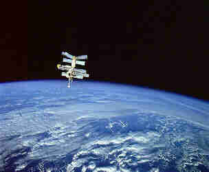
Particular 'satellites' are the manned space station (see picture above), like the former MIR or more recent the ISS, which are also fitted with various amateur equipments, like a packet-radio BBS and FM repeater. Very exceptionally, it is even possible to have a 2 way QSO with cosmonauts, like I did with the MIR some years ago and later with ISS! Normally, these space stations are workable with quite standard equipment - like a 2m VHF FM Rig with 10w output and a GP-antenna.
The Satellite station comprises following equipments:
- A VHF/UHF transceiver:
The transceiver is an ICOM IC-910H, which is controlled by the PC to take into account the doppler shift on up- and downlink due to the movement of the satellite. The power can be smoothly adjusted in order to access the satellite transponder with appropriated power.
- Antenna's
The antenna's are used for reception and transmission. As a matter of facts, on VHF and higher bands, they must be pointed towards the satellite, so a tracking system must be foreseen. I am using the IF-100 board which is PC-controlled and smoothly follows the 'birds'.
- Software
A good and user-friendly software is a must for convenient satellite operations. The software calculates transits, controls the RX/TX through CAT port, and steers the antenna tracking rotors (azimuth and elevation). Not to forget the possibility of keeping Kepler Elements updated and a very precise time synchronisation.
I am using since years the excellent software SATPC32 of Erich DK1TB (see www.dk1tb.de)


The station is built around the IC-910 H transceiver, operating in satellite mode.
- UPLINK on 2400 MHz:
- Transverter 70 cm --> 13 cm by SG-labs
- Small PA by Bert Modderman, powered by adjustable voltage step-up PCB (14 .. 28v), providing about 3W
- Helix 3 1/2 turns in "ice cone" antenna
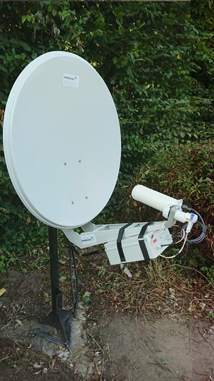
- Offset dish 180cm TRIAX
- DOWNLINK 10 GHz
- LNB Octagon, modified for external PLL reference frequency injection, providing output directly on 144 MHz
- PLL reference frequency by GPSDO Leo Bodnar
Between shack and all electronics outside (fitted in WT cabinet) only one coaxial cable RG213 30m long, over which all signals and DC power is running.
Small dish, 2x FT-819 transceivers (full duplex operation), Arduino CAT control, RF deck, power supply (230V AC and/or 13,8V DC) all boxed in PELICAN transport case, weight total 15 kg.
 QO-100 Portable satellite station. antenna can be mounted on the
carry case or on a clamp affixed to a table, or pedestal, up to 2m
distance
QO-100 Portable satellite station. antenna can be mounted on the
carry case or on a clamp affixed to a table, or pedestal, up to 2m
distance
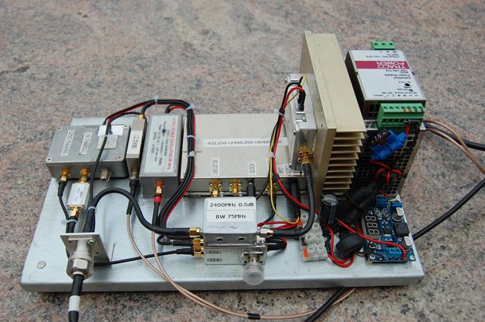
The RF deck with power supply. Connected to the transceiver deck by
one single (coax) cable, RG-58 up to 5m, RG-213 up to 30m
![]()
The up- & downlink transceivers with ARDUINO syncing unit & SSB voice
processor
The cause is the 4th harmonic of 2400,25 MHz which is on 9,601 GHz and overloads the very sensitive LNB. The trouble was cured by inserting a homebrew 2.4 GHz interdigital filter of 2 sections, this measured as 0,5 dB attenuation on 2,4 GHz with a BW of 75 MHz @ -3dB. Attenuation on 9.6 GHz was not measured, but will be very high.
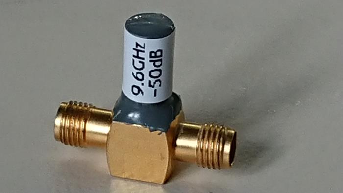
Other solution is presented by DH8AG in CQ-DL magazine, see pdf document. The 'T' part of a 3 way SMA connector was cut off with a Dremel fitted with miniature cut-off wheel , the resonance frequency then further adjusted by carefully grinding the center pin with ball shaped carving bit - so I didn't use the adjusting screw possibility. A tube was glued on top to protect the filter.
On HF/VHF, notch filters provide in general about 30 dB attenuation. The notch filter I constructed (see picture below) was measured on 9.601 MHz as -40 dB on it's own, when further damped by a coax line the attenuation (of the filter, excluding coax losses) was measured as 52 dB. Bandwith @ -3dB about 10 MHz.