ON6MU's
"Vipormutant" Antenna
RE-AHFV14P
Versatile Inexpensive Portable Multi-band Tunable Antenna
de ON6MU
revision 2
Features
What you need to build the "Vipormutant"
some low loss RG174 50 Ohm coax
carbon/ferrite bead or toroid (to act as a choke)
a few meters of 0,75mm enamelled copper wire to make the coil
About the "Vipormutant" antenna:
Well yes, one must have a name
HI...It is nothing more then a base coil loaded antenna, but with
a selector direct on the base to tune the antenna.
Most of us don't have the luxury of building a 1/4, 1/2 or even a
5/8 wavelength vertical antenna for HF. We have to settle for
something a little shorter. (A lot shorter, in the case of people
following the FCC's Part 15 rules, which limit them to 3 meters
in size.) Shorter vertical antennas can give acceptable (but not
spectacular) performance.
I needed a highly (HF) portable antenna to use with my FT-817
which should have the highest possible frequency range (also VHF)
and still compact enough to take along almost anywhere! The
antenna should be versatile enough to allow further
experimenting, to allow being mounted on a balcony, caravan,
outdoors etc... So I came up with a compact vertical (dismounted
no higher then 1 meter) with a "tuner" directly
connected to the antenna radiating element (the best possible
place a tuner can be).
The "Vipormutant" tuning principle gets energy into the
antenna on a wide range of frequencies, but the design of an
antenna is what controls what happens to the RF energy from
there. For some antennas, the antenna is simply not complete
without a radial system, or at least a counterpoise. Other types
of antennas need no RF ground system at all. Most reference books
on antennas provide solid guidance on radials and counterpoises,
but only for antennas cut to a specific frequency. When using the
"Vipormutant" it will also act like tuner and at the
best place a tuner should be: directly beneeth the antenna! So
the rules have to change somewhat because the
"Vipormutant" almost operates across the full range of
HF frequencies unto UHF. It doesn't need a counterpoise to work,
but the efficiency will increase when you do use it.
Considerations:
The coil/tuner
Wind 0,8mm enamelled copper wire
around the isolator (+- 16mm diamter) and make a tap every xx
turns (see fig. 2 and 3)
Fig.1
 Fig.2
Fig.2 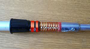 The coil
dimensions isn't too critical.
The coil
dimensions isn't too critical.
Relatively short antennas behave like lossy capacitors and
present a high impedance load to the transmitter due to the large
amount of capacitive reactance that is present. The loading coil
helps to tune out that reactance. Tuning out the reactance is
important because a tuned antenna will accept and radiate much
more power than a mismatched antenna.
When the loading coil is installed at the bottom of the vertical
radiator, we call it a "base loaded" antenna. Base
loading requires the smallest amount of inductance to achieve
resonance.
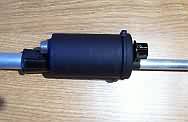
The shoke
Is made out of miniature 50 Ohm
coax (rg174) that goes a few turns through the carbon/ferrite
bead or toroid. You can also use a Snap-Together Ferrite Choke
Core.
If a ferrite is put over a cable which includes both signal and
return lines, it will have no effect on the signal
(differential-mode) current but it will increase the impedance to
common-mode currents. This is because the differential currents,
by definition, sum to zero in each wire pair and therefore there
is no net magnetic field. If there is no field, the ferrite is
invisible. But the common mode currents do produce a net magnetic
flux and this flux is concentrated in the bulk of the ferrite,
leading to an increased impedance for these currents only. The
choke should prevent any mantle currents flowing and should
decrease RFI.
The effectiveness can be increased by looping the cable several
times through the core, but the benefit is limited at higher
frequencies by the stray capacitance between the turns of the
cable.
Fig 3.
 4
turns
4
turns
Highlighted
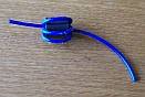
The base insulator
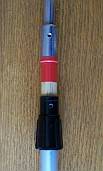
The vertical radiator
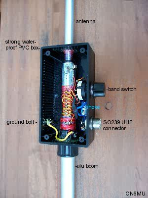
"driver" element and tuning box
I used a plastic box of 130x70x40mm. On top and bottom I drilled
a hole to fit the driver element (radiator of +/- 40cm length)and
boom (also +/- 40cm length).
On the side I drilled a hole for the rotary switch and the SO239
connector, whilest on the opposite side I drilled a hole to fit a
"ground" bolt where I can easily connect the
counterpoise and/or ground to if needed.
Fig 4
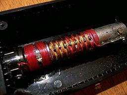
Fig 5
This is how things are connected inside the box:
Fig. 6
 Example
The rotary switch is used for tuning the antenna on each band.
The first position allows UHF/VHF ranges. Tuning is done by
sliding in/out of the elements.
The "lower" the switch (higher inductance) the lower
the resonance frequency of the antenna.
Remember, and this is important
too, to seal everything up so no moisture can penetrate the
antenna!
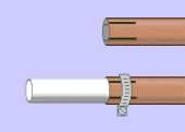
Because the radiating vertical antenna elements are made out of
separate pieces that fits inside each other and are tightened by
hose clamps, the construction isn't waterproof.
If you use a hollow isolating piece you need to to prevent
moisture from getting inside the box (via the places where the
elements are hold together). I've used a rubber
"stopper" that fits snugly on the bottom of the driver
element and glued tight.
Black paint finishes the job:
fig. 7
 using
a round box
using
a round box
In my first design I used a plastic box of 50mm diameter and 9 cm
heigh. On top I drilled two holes: one for the driver element
(radiator of 40cm) and a hole for the rotary switch (as was used
in the first prototype).
fig.8: The main
driver element and tuning unit finished
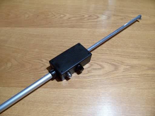
This allows it to be used on almost any boom or can be extended
to use with or without vertical elements!
Ideal for experimenting!
Featuring
Today
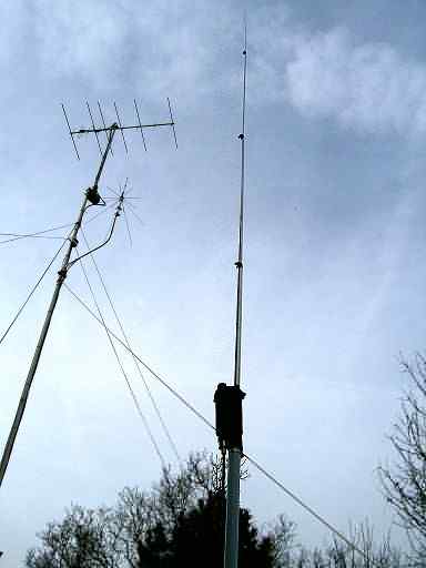
The antenna construction specs
All elements are made out of
aluminum.
Fig. 9
This makes the antenna effective
radiating elements a total length of 3 meters. The boom elements
can be chosen freely and on your needs. A short one (one element
of a meter), a medium sized one of several 1 meter tubes or none
at all! The bottom piece where the boom is "connected"
too is 40 cm and can/could be put directly in the ground (if made
pointed for sure). Or you could fix it in a umbrella stand. Use
your imagination HI.
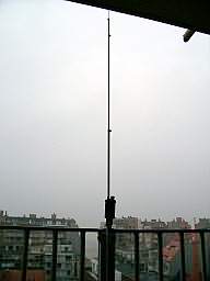
Examples of "Vipormutant's" utilization
Used it on a balcony:
This could cover even the lowest HF-bands!
Use it outdoors without grounding:
Use it outdoors as a shortened "dipole" balanced antenna
(rotary switch set approx. in the middle):
Frequencies below 7 MHz could easily be match 1:1 SWR if total length of the "dipole" > 4 meters
Further tuning can be done with selecting a different impedance using the rotary switch.
Different lengths of wire can be used (an example: one part 3 meter, the other 5 meter or more)
Use it outdoors with ground or counterpoise:
Radials and Counterpoises
basic purposes:
1. To improve the RF ground conductivity for the ground current
return path. Unless you live in a salt-water swamp, your ground
conductivity makes a very poor path for the return of ground
currents. This increases the ground losses and reduces the
efficiency of an antenna that needs a good RF ground.
2. To provide a counterbalance for the feed point of the antenna
to reduce RF radiation back to the radio room. The
"Vipormutant" changes the rules because there is no
single frequency that you will be operating on, so all of the
thumb rules for 1/4 and 1/2 wavelength radials don’t apply.
It is possible to be either a purist or a pragmatist in deciding
what radials to put in place.
3. Number of radials: More is better, up to a point. In carefully
controlled experiments, it has been proved that increasing the
number of radials from 2 to 15, or from 4 to 16, produces
significant increases in signal strength. Further increasing the
number of radials to 60 only produces 1 to 2 dB of increase in
field strength. Follow this link to see some of the empirical
data.
4. Where to put the radials: For a semi-permanent installation,
it is customary to bury the radials a few inches down in the
soil. This makes it much easier to mow and walk in the area
around the antenna. However, some experimenters have gotten an
improvement in performance by raising the radials and the antenna
base a few inches above the soil. Raising the antenna and ground
system several meters above the earth, for example by installing
the base of the antenna on a roof-top, can improve the antenna's
performance by reducing capacitive earth losses.
While the
"Vipormutant" will provide a good match with a poor RF
ground system which will will able you to transmit, your antenna
efficiency will be low. Nevertheless, by using a tuning circuit
directly at the antenna radiating element losses are kept to a
miminum. Getting the greatest efficiency out of your antenna
system needs a proper RF ground unless you’re using a
balanced antenna system
The efficiency of the
antenna increases by using a counterpoise. However, the antenna
can be tuned perfectly without!
| A comment from
George, SV2FNN Hello
Guy....I would like to convey my congratulations and my
thanks ... for your nice designs ... and especially for
the VIPERMUTANT ANTENNA.. ... Excellent contacts,,,,with
all over the planet..((the last 5 years))..with my
100w...and fed with 23m 75ohm tv coaxial !!!....I make 2
of them....one 20-6m....and another for 40m band...3,6
vertical...+ 5,5m wire horizontal 5m above
ground....!!!!!!!!!!!!!....excellent QSO for local....and
DX...(( YB,,,JH,,))..!! |
Don't
forget to check these out:
.ON6MU
Homebrew projects
.Radioamateur related projects
.ON6MU
Ham mods
.Modifications of transceivers
73"
Have fun and my best 73"
Guy, ON6MU
https://www.qsl.net/on6mu
Comments, pictures or experiences with my antenna are always welcome!
![]()