1Watt AM(cw) Transmitter
for the 10 meterband
RE-TX1HF10
By Guy, de ON6MU
Revision v1.6 (Jan 2012)
![]()
1Watt
AM(cw) Transmitter
for the 10 meterband
RE-TX1HF10
By Guy, de ON6MU
Revision v1.6 (Jan
2012)
About the 1watt AM/CW 10-meter band transmitter RE-TX1HF10
In this project, you will make a
simple 3-stage low-power broadcast-type circuit, using a crystal
oscillator integrated circuit and an a collector modulated AM
oscillator with amplifier. You can connect the circuit to the an
electred microphone or amplified dynamic microphone. Using
an electred microphone is shown (in gray) in the diagram below.
(no amplified dynamic microphone has a to low output voltage to
work. at least 100mv is needed). You could also add a LF preamp
stage of one transistor to allow connecting a dynamic microphone
directly.
You'll see that you can receive the signal through the air with
almost any AM radio receiver. Although the circuits used in radio
stations for AM receiving are far more complicated, this
nevertheless gives a basic idea of the concept behind a principle
transmitter. Plus it is a lot of fun when you actually have it
working!
Remember that transmitting on the 10 meter band you'll need a
valid radioamateur license!!
A wide range of different circuits have been used for AM, but one
of the simplest circuits uses collector modulation applied via
(for example) a transformer, while it is perfectly possible to
create good designs using solid-state electronics as I applied
here (T1 BC557).
The transmitter is build as a Colpitts Oscillator with a BSX20
transistor. HF-output of the oscillator is approx. 50 mW,
depending on the supply voltage of 8 to 16 Volts. This is
amplified by the BD135 and brings the power up to approx. 1 watt
@ 14volts with maximum modulation. The transmit frequency is
stabilized with the 28Mhz crystal. A slight detuning of approx
1kc is possible when using a 120pF trimmer capacitor for C8. The
oscillator signal is taken from the collector of T2 and guided to
the input of T3 which output is lead via an L-filter and low-pass
PII filter circuit cleaning up the signal pretty good and
ensuring spectral purity. The oscillator is keyed by T1 and the
morse key (S). By keying the morse-key T1 is not been used for
modulation and is biased, hence lets T2 freely oscillate.
The oscillator uses a single coil and crystal. The coil is tuned to the output frequency, which may correspond to the crystal frequency, or a harmonic.
AM
![]()
Amplitude
Modulation (AM) is a process in which the amplitude of a radio
frequency current is made to vary and modify by impressing an
audio frequency current on it.
This was the first type of modulation used for communicating
signals from one point to another and is still the simplest to
understand.
A radio frequency current has a constant amplitude in absence of
modulation and this constant amplitude RF carries no information,
i.e. no audio intelligence and is of no use to radio telephone
(voice communication), but has application in morse code
communication.
In its basic form, amplitude modulation produces a signal with
power concentrated at the carrier frequency and in two adjacent
sidebands. Each sideband is equal in bandwidth to that of the
modulating signal and is a mirror image of the other. Thus, most
of the power output by an AM transmitter is effectively wasted:
half the power is concentrated at the carrier frequency, which
carries no useful information (beyond the fact that a signal is
present); the remaining power is split between two identical
sidebands, only one of which is needed.
CW
CW is the simplest form of modulation. The output of the
transmitter is switched on and off, typically to form the
characters of the Morse code.
CW transmitters are simple and inexpensive, and the transmitted
CW signal doesn't occupy much frequency space (usually less than
500 Hz). However, the CW signals will be difficult to hear on a
normal receiver; you'll just hear the faint quieting of the
background noise as the CW signals are transmitted. To overcome
this problem, shortwave and ham radio receivers include a beat
frequency oscillator (BFO) circuit. The BFO circuit produces an
internally-generated second carrier that "beats"
against the received CW signal, producing a tone that turns on
and off in step with the received CW signal. This is how Morse
code signals are received on shortwave.
Although this design is primarely designed for AM, it can be used
for CW by keying S and so powering the oscillator. You can remove
the modulation section all together if you use it only for CW.
The amplifier (T3) is always fed with 12...16 volts Vcc and
doesn't need to be switch off together with the oscillator.
If you only gonna use this transmitter for CW, then you can leave out the modulater section (T1). But remember that there is a 3 volt difference between Vcc and the voltage on the oscillator. So with modulator 12 Vcc is 9 volts on T2, without T1 ofcourse 12v also.
RF Oscillator
Is been carried out by T2 (NPN BSX20). This is the stage
where the carrier frequency intended to be used is generated by
means of Crystal Oscillator Circuitry or capacitance-inductance
based Variable Frequency Oscillator (VFO). The RF oscillator is
designed to have frequency stability (Xtal) and power delivered
from it is of little importance, although it delivers 50mW@14v ,
hence can be operated with low voltage power supply with no
dissipation of heat.
You could add a switch (not
recommended, but if you do, use very short connections) to select
different Xtal's (frequencies). You could also use a more
effective diode-based switch I've build here. This hasn't got the problems with
longer connections at all.
Injection of signal of an external tuneable oscillator to trigger T2 to oscillate is possible by removing the Xtal and connecting C8 to your oscillator.
Filter
RF power amplification is also done here and this stage is
coupled to the antenna system through antenna impedance matching
circuitry (L1/L3,C16,C18). Care is taken at this stage so that no
harmonic frequency is generated which will cause interference in
adjacent band (splatter) on other bands (L3/L4,C16...C20). This
3-element L-type narrow bandpass filter circuit and a lowpass
filter for the desired frequency cleans out any remaining
harmonic signals very efficiently.
Modulator
Is done by T1 (PNP BC557). Audio information is impressed
upon the carrier frequency at this stage. Do to selective
components circuits (R10, R11, C25, C3, C4, C5, C6, C7) the voice
component frequencies are enhanced, whilest others are suppressed
(bandwidth +- 5kc/side).
Collector modulation is applied here. The efficiency isn't 100%,
but it does keep the simplicity of the design intact. Modulation
depth can be controled by changing R2 and R3.
Why overmodulation is not desirable?..
Overmodulation is not desirable, i.e. modulation should not
exceed 100 %, because if modulation exceeds 100 % there is an
interval during the audio cycle when the RF carrier is removed
completely from the air thus producing distortion in the
transmission.
Housing/shielding
The whole circuit needs to be mounted in an
all-metal/aluminum case. If you're unable to obtain an all-metal
case, then use a roll of self-sticking aluminum tape (available
from your hardware store) or PVC box painted with graphite paint.
Just make sure that all individual pieces of aluminum-tape (or
the graphite paint) are conducting with each other. Works fine.
More power
You can connect the output to my power MOSFET based
10-meterband power amplifier wich should cranck up the power to
approx. 6 watt. You'll find it here.
Mute: Use the transmitter
with your receiver
If you put a relay, or better a transistor switch to mute
your receiver (if equiped) you can easily make a QSO HI. A simple
BC338, 2N2222 at pin a" with the base biased with a 100k
resistor, emmitor at the gnd and the collector fed to your
receiver's mute input works fine. Or you can use a 12v relay...
Every time you PTT the transistor (or when using a relay, the
switch) is "shortened" between the ground, hence muting
your receiver (again; if your receiver has mute capabilities).
This is shown in the diagram below.
Specifications
Peak Frequency range: 28Mc...30Mc
Output RF PEP
power: approx.
1W@14v
measured with maximum modulation depth
AM modulated. Modulation depth can be controled by changing R2 and R3. (CW if keyed)
Adjustable output impedance to 50 Ohms
Band-pass type harmonic L-filter + low-pass PII filter
Usable voltages: Vcc 10 - 16 volts
Average current: I= 120mA
Xtal oscillator, 28.xxx Xtal
Adjustable frequency of 2Kc (if C8 is replaced with a 120pF trimmer)
Injectable with external oscillator *see text
LF input +/-
100mV @ 1K
Schematic 10-meter band AM transmitter: fig1
Parts list 10-meterband AM / CW transmitter
T1 BC557 (modulator)
T2 BSX20 oscillator (2N2219. BC109 works also, but little less power)
T3 BD135 amplifier (with heat sink isolated from the transistor)
T4 2N2222, BC338 mute
C1 = 100nF
C2 = 47uF/16v (tantal)
C3 = 2.2 uF/50v (changed in rev v1.5)
C4 = 33nF (polyester) (changed in rev1.5)
C5 = 10nF (polyester)
C6 = 47nF (changed in rev1.5 )
C7 = 4.7uF/50v
C8 = 10nF
C9 = 0...22pF (60pf for 27Mc)
C10 = 120pF
C11 = 56pF
C12 = 470uF/16v
C13 = 100nF
C14 = 47nF
C15 = 470pF
C16 = 6...40pF
C17 = 12pF
C18 = 120pF
C19 = 56pF
C20 = 100pF
C21 = 470pF
C22 = 100nF
C23 = 10pF*(added in revision v1.2)
C25 = 0,47uF (polyester, added in rev1.5)
C26 = 47uF tantal (added in rev1.6)
R1 3k9
R2 3k9
R3 4k7 (*rev1.6)
R4 6k8 (*rev1.6)
R5 1k2
R6 220
R7 12
R8 100k
R9 4k7* (added in revision 1.4)
R10 270 (added in rev1.5)
R11 390 (added in rev1.5)
Ls1, Ls2 =
470 1/2 watt carbon!, 0,2 Cul turned 3 times over the
entire length of the resistor (or +/- 2.7uH inductor) or
use ferite bead
note: you can also use a ferrite core of 3...4mm instead
of a carbon resistor
L1 = 0.8mm insulated copper wire, 9 turns close together, 7mm inside diameter (or 7 turns of 0.8mm wire around 8mm support (it should correspond to about 250nH))
L2 = 0.8mm insulated copper wire, 12 turns close together, 6mm inside diameter
L3 = 0.8mm insulated copper wire, 13 turns close together, 7mm inside diameter
L4 = 0.8mm insulated copper wire, 7 turns close together, 7mm inside diameter
L5 = 100uH inductor (*added in revision 1.3)
Xtal fundamental frequency or overtone for your desired frequency (28...30Mc)
C4, C5, C6, C25 polyester film capacitors
(L6 and C24 removed in rev1.6)
top view
Ls1,Ls2,Ls3
Revision 1.2
C21 added to prevent the oscillator from oscillating at 2e
harmonic when not connected to the amp-stage. If the
oscillator is coupled/connected (via C11) with the input stage of
the amplifier as designed (even if the amp stage is not powered)
2e harmonic oscillations are prevented even without C21.
To resolve this issue (in any situation) C21 has been added.
C5 was missing from the partslist
R2,R3,R4 had slight diviated values from standard available
resistors (thanks Medard from Switserland!)
Revision 1.3
To improve T2 BIAS: R5 was 2k2, now 1k2. L5 added (100uH)
To improve T1 BIAS: R1 was 4k7, now 3k9
C12 changed
Revision 1.4
Ls1 (former between C6 and C7) is replaced by 100uH inductor
R9 added to improve modulation
Revision 1.5 (May 2009)
R10, R11, C25 added, and C3,C4,C6,C24 changed values: to
improve linearity
Note:
Always use a dummy load for testing and adjusting the
transmitter!!!
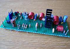
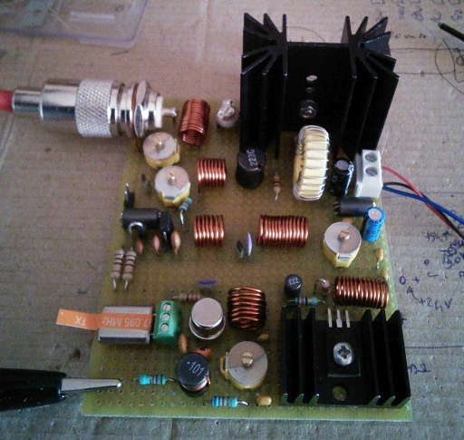
Salvatore Polito
made the the 1 watt 27/28mc transmitter together with the 5 watt amplifer:
Antenna's
It's important to
use a correct designed antenna according to band you would like
to operate, or at least use a good antenna tuner to match the
antenna (protecting your transmitter and proventing
harmonics/interference...). Several examples can be found on my
website and all across the Web. A dipole is always a good
alternative (total length = 150/freq - 5%).
The performance (distance relative to you RF power) of your
antenna is as importent (if not more) as the RF power you
transmit! A dummy load gives also a perfect 1:1 SWR, but you wont
get any farther then the street you live in HI. Finally,
athmospheric conditions (D-,E-,F-layers depending on the
frequency you're using) is equally important to be able to make
DX QSO's.
Remember that transmitting on 10 meter band (or building and using the transmitter) needs a valid radioamateur license!
12 meterband AM / CW transmitter project