AM/FM/CW RF Power Amplifier
for the HF 10 or 11 meterband (28Mc/27Mc)
RE-PA5HF10 and RE-PA7HF10
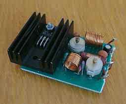
prototype
By Guy, de ON6MU
![]()
AM/FM/CW
RF Power Amplifier
for the HF 10 or 11 meterband (28Mc/27Mc)
RE-PA5HF10 and RE-PA7HF10
prototype
By Guy, de ON6MU
About the 10-meterband HF amplifiers RE-PA5HF10
This project and your efforts will provide you with a 0.5 watt input to 5 watt output. The linear amplifiers are ment for use with QRP CW/FM/AM transmitters on the 10meter amateur band (but can also be tuned for 27Mc) can be powered from a 12 volt DC supply. The design is a good balance between output power, physical size. The completed amplifier will reward the builder with a clean, more powerful output signal for a QRP rig when radio conditions become marginal. The first project uses a "classic" RF transistor. The second project uses a MOSFET and can deliver 7 watts.
Bias
Power amplifiers used in base stations require biasing for
proper RF performance on SSB. The first design doesn't use it as
it is designed for carrier modulation modes (like AM,FM,CW). It
can be used for SSB, but the modulation won't be clean and
smooth. It will sound a bit like those Zetagi amps. The second
design (RE-PA7HF10) does use proper BIAS applied to Q1 to have
clean proper and correct SSB modulation using this amplifier.
Filter
RF purity and harmonic suppression is done here. Also allowing
the transistor to be coupled to the antenna system through
antenna impedance matching circuitry (C5,6,7 and L2). Care is
taken at this stage so that no harmonic frequency is generated
which will cause interference in adjacent band (splatter) on
other bands. This 3-element L-type bandpass filter circuit cleans
out any remaining harmonic signals.
To allow maximum filtering of the 2nd harmonic (56Mc) we could
add a parallel LC blocking filter tuned to 56Mc. For 27Mc we need
a 54Mc blocking filter.
For 28Mc add in series with the output a coil L=5turns, 0.9mm,
7mm inside diameter and parallel on this coil a 47pF capacitor
(or use a trimmer of 60pF to allow peaking the filter to the band
you want to use).
Another PI-filter would be recommended too. The reason for this
project is to show the working principle of a non-biased
transistor based RF amp, so I kept it simple to the bare
necessities.
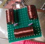
Salvatore Polito made an
excellent filter that supresses the 2nd harmonic (base freq x 2)
-40dB:
The inductors are air inductors made with 0.8mm enameled wire
over a 7mm support:
- 514nH => 12.5 turns
- 838nH => 18 turns
Housing/shielding
The whole circuit needs to be mounted in an
all-metal/aluminum case. If you're unable to obtain an all-metal
case, then use a roll of self-sticking aluminum tape (available
from your hardware store) or PVC box painted with graphite paint.
Just make sure that all individual pieces of aluminum-tape (or
the graphite paint) are conducting with each other. Works fine.
I made this amplifier on a board of only 6cm x 4cm including the
heatsink!
RE-PA5HF10: 10-meterband Amplifier settings
Connect a 50 Ohm
dummyload and a powermeter on the output.
Connect a SWR-meter between the input of the amp and your
transmitter (be sure the transmitter is set to low power +/-500mW
and set to your desired centre frequency).
Set C2 and C5 to the middle. After carefully mounting all parts
and using as short as possible connections between the parts,
gently add voltage to the amplifier while checking the current.
The only current you should see is a the liddle idle current of
Q1. Increase the voltage to 12 volts. Check current again. It
should (at this stage) be lower then +/- 2mA.
Still all working as planned? Excellent! Now carefully turn C2
till you get maximum the best SWR and output power (whilest
checking the input SWR on your transceiver or SWR meter). And
finally tune C5 and C7 to maximum power. If needed re-tune C2 and
C5 till you reached the maximum and best SWR on the centre
frequency. Current should be around 0.5 Amp +/- @ 14v (depending
on the voltage and input power).
Do not forget to mount Q1 on a heat sink isolated electrically
from the transistor.
Parts list 10-meterband power amplifier
Q1 BD135 (with proper heatsink isolated from the transistor)
C1 10p
C2 40pF trimmer
C3 56p
C4 560p
C5 50pF trimmer
C6 33pF
C7 50pF trimmer
C8 10nF
C9 10uF
C10 100nF
C12 47uF
R1 1k 1/2 watt carbon (optional: if the driver needs a non-conductive load. Can usually be left out)
R2 220
R3 1k 1/2watt carbon (you can use a ferrite core of 3...4mm if no carbon resistor is available)
L1 = 0.9mm Cul (insulated copper wire), 7.5 turns close together, 7mm inside diameter
L2 = 0.9mm Cul (insulated copper wire), 13 turns close together, 7mm inside diameter
Dr1 = 10uH inductor or 0,4mm Cul (insulated copper wire), 60 turns close together over a 1k 1/2 watt carbon resistor (you can use a ferrite core of 3...4mm if no carbon resistor is available)
Dr2 = ferrite bead with a few turns of wire
Dr3 =
1.5uH...2uH inductor or 0,4mm Cul (insulated copper
wire), 30 turns close together over a 1watt 10k carbon
resistor (you can use a ferrite core of 3...4mm if no
carbon resistor is available)
.........or use a toroid T80-6 (yellow) with
18.5 turns of 0.5mm silver plated wired (Thanks to
Salvatore Polito).
Dr1
Note:
Always use a dummy load for testing and adjusting the
amplifier!!!
Specifications RE-PA5HF10
Tuneable frequency range: 26Mc...30Mc
Output RF
power: at
least 3.5W @ 13.8v - 5W@16v
measured at maximum modulation depth
AM/CW/FM (SSB with modulation Q limitations)
Adjustable output impedance to 50 Ohms
Adjustable input impedance to 50 Ohms
Efficient band-pass type harmonic L-filter filter at the output
Efficient band-pass type harmonic L-filter filter at the input
Usable voltages: Vcc 10 - 16 volts
Average current I: +/- 0.5A @ 13.8 v
VSWR overload resistant (not infinite)
Can be used without complex BIAS if only needed for CW/AM/FM/FSK type modulation
Compact and easy design (only 6cm x 4cm with heatsink)
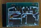
Salvatore Polito made
the amplifer together with the 1 watt 27/28mc transmitter:

Allmode RF Power
Amplifier for the 10 meterband (28...30Mc)
RE-PA10HF10
By Guy, de ON6MU
About the 10-meter band HF amplifier RE-PA7HF10
All is already explained above (17-meter band amplifier): Read it here
10-meterband Amplifier settings
Connect a 50 Ohm
dummyload and a powermeter on the output.
Connect a SWR-meter between the input of the amp and your
transmitter (be sure the transmitter is set to low power +/-500mW
and set to your desired centre frequency).
Set P1 to the minimum (ground potential).
Set C3 to the middle. After carefully mounting all parts and
using as short as possible connections between the parts, gently
add voltage to the amplifier while checking the current. The only
current you should see is a the liddle idle current of Q1.
Increase the voltage to 12 volts. Check current again. It should
(at this stage) be lower then +/- 2mA.
Now gently turn P1 till you get approx. 25 mA. Depending on the
type of MOSFET the BIAS current can vary somewhat.
Do not forget to mount T1 on a heat sink isolated but electrically from the MOSFET.
If you plan to use only FM/AM modulation then set P1 to 2mA or less, although the design allows you to set the BIAS to +/-25mA and use it in all modulation modes.
Note:
Always use a dummy load for testing and adjusting the
amplifier!!!
Specifications
Peak Frequency range: 27Mc...29Mc
Output RF power: at least 7W @ 13.8v
Input power 0.7watt max
All modulation modes
High efficient band-pass 9-element harmonic block- lowpass PII filter
Usable voltages: Vcc 10 - 18 volts
VSWR overload resistant (not infinite)
Antenna's
It's important to
use a correct designed antenna according to band you would like
to operate, or at least use a good antenna tuner to match the
antenna (protecting your transmitter and proventing
harmonics/interference...). Several examples can be found on my
website and all across the Web. A dipole is always a good
alternative (total length = 150/freq - 5%).
The performance (distance relative to you RF power) of your
antenna is as importent (if not more) as the RF power you
transmit! A dummy load gives also a perfect 1:1 SWR, but you wont
get any farther then the street you live in HI. Finally,
athmospheric conditions (D-,E-,F-layers depending on the
frequency you're using) is equally important to be able to make
DX QSO's.
Related
Remember that transmitting and/or using an power levels higher then your local license permit is illegal without a valid radioamateur license!
Another related
project:1watt 10 meterband transmitter project