VHF 1/2wave vertical antenna for the 6-meterband (50 Mhz)
RE-A50V12

By Guy, de ON6MU
![]()
VHF
1/2wave vertical antenna for the 6-meterband (50 Mhz)
RE-A50V12

By Guy, de ON6MU
Schematic fig1
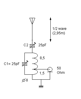
1/2 wave antenna principle
A
much better type of antenna then a simple quatre wave and that
has more gain is the 1/2 wavelength vertical. We know that the
impedance of the 1/2 dipole is 70 Ohms when we attach the coax in
the middle, but what if we were to attach our coax directly to
the end? The impedance at this point is high, very high, so we
must make a matching device to match the antennas impedance to
the 50 Ohm coax. What would happen if we did not use this
matching device? Well...you would know that this would result in
a very very high SWR.
The bandwidth of these antennas are good, they can easily span
the entire 50Mc band and more with a low SWR. But, in this
design, the bandwidth is limited to approx. 600kc (without
re-tuning C1 or C2). This allows you to tweak the antenna to your
desired band and avoid interference and reduce intermodulation.
The antenna and ground are connected across the tuned circuit
while a 50-ohm coaxial cable is connected to taps on the
inductor. The tuned circuit presents a high impedance to the
antenna and the tapped inductor steps this impedance down to 50
ohms. Adjusting the tuning capacitor tunes out slight reactance
variation if the antenna is not an exact electrical
half-wavelength.
Parts list
4 pieces of 1
meter alu or copper tubing:
- one 18 mm diameter
- one 15 mm diameter
- one 12 mm diameter
- one 10 or 8 mm diameter
1 female PL 259 chassis
some cul wire (isolated wire like from a transformer etc.) of 0,8 mm thick
a coil holder of 8 mm diameter
two 25pF regulable capacitors
A robust PVC box of approx 30x50x18 mm and 2mm or more thick
a piece of
hard insulating material that snuggly fits inside the
base tube, like:
fyberglass, nylon, hard pvc, hard wood, bamboo etc... as
long as it's very strong, stress and weather resistant.
and a few
innox hose clamps
Note: there are many ways to
build your antenna and I'm sure some can come up with better
mechanical designs then described here although the design and
material used here is cheap and easy to find. Also, the diameters
of the tubing described here is not too critical.
Links of interest:
The antenna
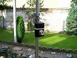
Construction:
The vertical itself is constructed out of four
overlapping sections of aluminum tube whose sizes are
given.
- saw the 1 meter 18 mm alu tube in half. One part (50
cm) will be used as a boom and the other as the first
part (also 50cm) of the antenna.
- saw some grooves (approx 1,5 cm) in both halves of the
tube to allow a hose clamp to tighten everything up.
- same goes for the other tubes that fits inside
eachother. All tubes are firmly fixed together by using
hose clamps.
- Measure from the base up 2,95 meters. You can alwyas
tune the antenna to its best SWR by sliding the top tube
in or out.
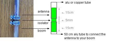
- saw a piece of that hard insulating material of your
choice and fit it 10 cm in the antenna and boom part and
leave a gap of 3 mm between them.
- hammer down one end of each of the 3 radials ( 3 x 22
cm) so it becomes a bit flatten. This will make things
easier to screw tight with the hose clamp. These radials
are fitted on the boom section.
The little
black box:
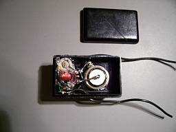
Here is where all the secrets are stored HI. I used a
little plastic box where I placed the LC-circuit and the
PL connector.
I also drilled two little holes where you can regulate
the two capacitors with an little isolated screwdriver.
Afterwards you can seal the holes up to prevent moisture
from entering the box.
The LC
tank-circuit:
- Wind 10 turns of 0,8mm cul wire around the 8mm coil
holder and make a tap at 1,5 turns. There is no spacing
between the windings.
- The smallest part (the "cold side" 1,5 turns)
of the coil is where your centre part of the
connecor/coax is connected to. The above schematic shows
how.
As you can
see there are two wires comming out of the box (which
contains the LC): one for the antenna and the other for
the ground (being the connecting boom piece).
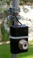
Connect the
wires accordingly and be sure to seal everything up.
Tuning:
- Get your old (t)rusty SWR-meter and and some 50 Ohms
coax and connect your transceiver to it.
- Set the two capacitors to halfway to start with.
- Mount your antenna temporary 1,5 meters from the ground
for the first tests and measure the antenna length (the
boom piece NOT included) at 2,95 meters and try to ground
the boom.
- Find a CLEAR frequency and set your transceiver to
MINIMUM possible power and use a carrier type modulation
(CW, AM, FM).
- Tune C1, which is the most important and critical
capacitor, till the SWR gets a s low as possible on your
desired centre frequency (51 Mc)
- Then tune C2 till the SWR is even more lowered or even
1:1.
- Repeat the last two steps at location if needed
- Fine tuning your antenna can be done by sliding the
tubes in or out. Sometimes when your place your antenna
higher or when the antenna has obstacles in its proximity
the SWR can vary from the one you noted first. Raising or
lowering the length of the antenna should fix it.
Highlighted
Specifications ON6MU Vertical Antenna RE-A50V12
Total length (including the 50cm mounting boom piece): 3,5m (2,95m effective)
centre frequency: 51 Mhz
bandwidth: 2 Mhz
maximum tunable frequency range: 49...53 MHz+-
impedance: 50 Ohms
Gain: 3,6 dBi
Maximum power using the components described: 20 watt
NO counterpoise or radials needed if the boom is grounded or the boom length is >= 1,5m
DC grounded (no static buildup)
Height: 2,95m
If needed, it
can be disassembled into a very small bundle no longer
than the longest element.
Be sure to seal everything up to avoid moisture, corrosion etc...
5/8 vertical
groundplane antenna for 50MHz
RE-A50V58
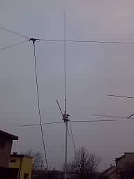
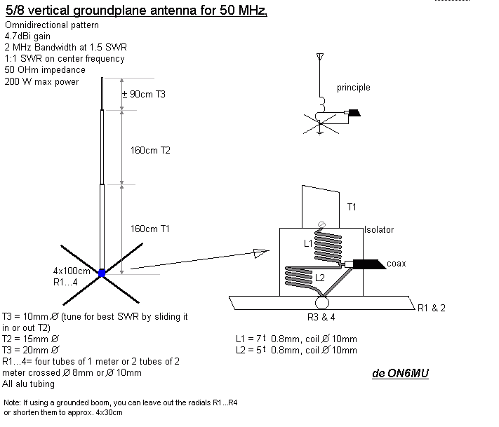
This is how Greg, SP5LGN
constructed my 5/8 lambda 6-meter GP antenna:

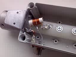
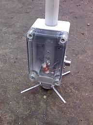
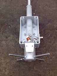
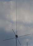
Click to enlarge
Many thanks Greg!
How Horacio
LU9DFN made it:

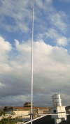
Click to enlarge
Many thanks Horacio!
SWR:
You can fine-tune the SWR to peak in the bandsection you are
planning to use the 5/8 groundplane antenna by:
- shorten or lengten the radiating element (vertical section)
- shorten the radials
- experiment with the coil spacing
| Today's specials: |
.ON6MU
Homebrew projects
.Radioamateur related projects
.ON6MU
Ham mods
.Modifications of transceivers
PA3BEN
sent me a lot of pics on how to convert an old CB antenna using
my schematic (shown here above) for 50Mc! I've put here 2 resized
pics (do to lack of webspace, sorry):
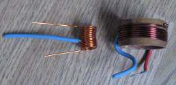
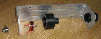
Thanks Ben!
Please take a look at my 50mc wide-spaced yagi antenna