Long Wave, Medium Wave and
Shortwave Radio Experiments
![]()
Long
Wave, Medium Wave and
Shortwave Radio Experiments
1)
Attempt to make a general coverage receiver (RE-RX1LM/HF)
LW, MW
and SW bands
 rev1.1
About RX1LM/HF revision 2.0 date aug/2019
This
is a compact three transistor regenerative general coverage
receiver with fixed feedback. It's based on the principle of the
ZN414 only it can handle higher coverage. The sensitivity and
selectivity is relative good (especially on the LF and MW bands)
as can be expected with this "simple" design. The
reception on the broadcast bands, LW(longwave) &
MW(mediumwave) needs no external antenna! Just a ferrite rod
which can be recovered from an old portable MW/LW radio which
tuned from approximately 540 - 1600kHz on MW and 140kHz-240kHz
for LW. If you have an old MW/LW (portable) radio you'll wont
need to make your own coils for those bands if you use those.
Remember: the longer the ferrite core the better MW/LW reception.
An AM radio receiver is fundamentally a very simple device. In
its simplest form, a resonant circuit builds up a signal if there
is one in space at the frequency to which it is tuned. A crystal
(galena) then rectifies the signal, which reproduces the
modulation. All the energy comes from the received
electromagnetic wave. A good receiver must combine sensitivity
and selectivity. Sensitivity is obtained by amplification in
several stages, while selectivity is obtained by a narrow
bandwidth of the amplifiers. There is a severe problem if the
receiver must tune over a reasonable interval, such as the
medium-wave broadcast band from 550 kHz to 1.65 MHz. The filters
of the several stages of amplification cannot track well enough
as their frequency is varied if the bandwidth is narrow, so one
must choose between sensitivity and selectivity in such a
tuned-RF receiver. There are other problems as well, such as the
variation in selectivity as the circuits are tuned over a wide
range.
It doesn't need a external power supply as the total current is
very low (total 12mA) and can be fed with just 3 (chargeable)
batteries.
Transistor Q3 has a dual purpose; it performs demodulation of the
RF carrier whilst at the same time, amplifying the audio signal.
Audio level varies on the strength of the received station but I
had typically 10-50 mV. This will directly drive the TDA7052 and
drives a 8 Ohm speaker up to 0.65 watt @ 6volts. When oscillation
should occur (and we don't want that) try installing C15.
Q1 and Q2 form a compund transistor pair featuring high gain and
very high input impedance. This is necessary so as not to unduly
load the tank circuit. Q1 operates in emitter follower, Q2 common
emitter, self stabilizing bias is via the 56k resistor, the 150pF
capacitor and the tuning coil.
P1 set the audio volume.
All connections should be short, a veroboard or tagstrip layout
are suitable if the desired frequency isn't too high. The tuning
capacitor has fixed and moving plates where the moving plates
should be connected to the "cold" end of the tank
circuit, this is the base of Q1, and the fixed plates to the
"hot end" of the coil, the juction of 56k/150p/100n. If
connections on the capacitor are reversed, then moving your hand
near the capacitor will cause unwanted stability and oscillation.
Switch between the coils (being the frequency bands) with S1. The tapping points on the coil allow the set to be tuned to different frequencies by adjusting the position of tap-switch S1.
By
using the transistors as a darlington pair it will have high
amplification, but the bandwidth will suffer. This compound
structure of design acts in such a way that the current amplified
by the first transistor is amplified further by the second one.
This configuration gives a much higher current gain than each
transistor taken separately.
It's important to use transistors with high usable frequency
(experimentation with RF capable transistors or even VHF is
educational and could improve this design further).
You can also replace the "RF amplifier/demodulator unit" with a ZN414/MK484 as shown on lower on this page but without the BC109 LF amp, or you can leave it and change the 10k pot with a 10k trim potentiometer to be able to adjust the volume that is fed to the TD7052. One thing though...The ZN414 does not handle LW very well (bad is more appropiate).
Shortwave?
Fig1: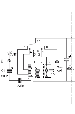 I have experimented with this radio and it could
reach up to 24MHz. However, sensitivity and selectivity suffers
as frequency goes up. It also needs an external antenna when
wondering about on those shortwave frequencies. I would also
recommend to use a variable C1 in series with the antenna
connector to avoid the receiver being saturated at higher
frequencies (shortwave) when using a longwire or any other
"large" antenna that isn't resonant. Using a real
antenna tuner would be even better... The sensitivity is not as
good as on MW and LW though, nor is the selectivity. I've put a
RCA/Cinch-connector (or better, a BNC-connector) at the band
switch to allow experiments with different types of coils for
different frequency ranges.
I have experimented with this radio and it could
reach up to 24MHz. However, sensitivity and selectivity suffers
as frequency goes up. It also needs an external antenna when
wondering about on those shortwave frequencies. I would also
recommend to use a variable C1 in series with the antenna
connector to avoid the receiver being saturated at higher
frequencies (shortwave) when using a longwire or any other
"large" antenna that isn't resonant. Using a real
antenna tuner would be even better... The sensitivity is not as
good as on MW and LW though, nor is the selectivity. I've put a
RCA/Cinch-connector (or better, a BNC-connector) at the band
switch to allow experiments with different types of coils for
different frequency ranges.
Frequency
coverage RX1LM/HF
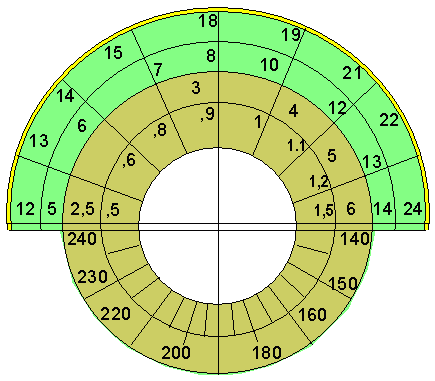
LW : 140 - 240 KHz (good)
MW: 520 -1600 KHz (good up to 3Mc)
Experimental:
SW1: 2500 - 6000 KHz (moderate)
SW2: 5 Mhz - 14 MHz (moderate)
SW3: 12 MHz - 24 MHz (low)
Mode: AM
Schematic
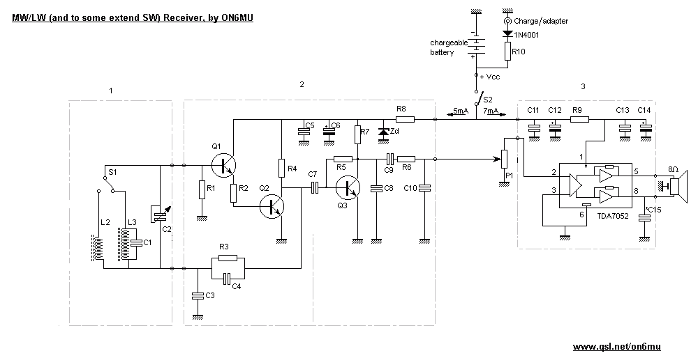
Fig.2
Tuning unit |
RF amplifier/demodulator unit |
LF output amplifier |
Details - Coils
L2: 310 uH, 65 turns on a
9/10mm ferrite rod OR LW 'loopstick' antenna also
'recycled' from an old transistor radio (both L2 and L3 are on
the same ferrite core)
L3: 4 mH, 550
turns on a 9/10mm ferrite rod OR MW 'loopstick' antenna
scrapped from an old transistor radio
The loopstick antenna coil is best wound on a bit of cardboard or plastic tube around the ferrite rod. The coil can then be slid along the rod to adjust the tuning range. Use this to set the low-frequency end of the band. If you need to set the upper end of the band then place a capacitor across the tuning cap and re-adjust the low end of the band again (in schematic L3 + 150pF). Experiment.
S1: 2 way switch (MW/LW band selection)
For
SW experiments:
*L1: total of 37 turns of
0.65mm on a 18mm diameter plastic tube of 30 mm height:
taps at 24 turns, 8 turns, 3 turns, 2 turns
see fig.2
S1: 6 position rotary switch* or 2 position if only build for MW and LW
Component List
Q1, Q2, Q3 = 2N3904
Zd = 6 volt
P1 = 10k
R1 = 1M
R2 = 220
R3 = 56k...100k (experiment)
R4 = 3k2
R5 = 480k
R6 = 1k
R7 = 4k7
R8 = 100
R9 = 4R7
R10 = 47 1watt * value also depends on the maximum charging current of the used battery and the applied voltage!
C1 = 150*
C2 = 10...280pF
C3,C5,C8,C11,C13 = 100nF
C4 = 150pF
C6 = 100uF 25v
C7 = 22nF
C9 = 220nF
C10 = 47nF
C12 = 470uF 25v
C14 = 220uF
C15 = 100nF * optional: if the IC should oscillate
Specs
Frequency range: 140 kHz - 4000 KHz (maximum limit +/- 24 MHz). LW & MW bands needs no external antenna.
AM modulation detection
U = 3...9 volts *Battery or external power operated
5 x 1.2 volt chargeable batteries or 1 x 9v chargeable battery
I = 13mA @ 6volts
Output LF power: 650mW @ 6volts
PL259 connector for external antenna (used for the shortwave bands)
The receiver sensitivity and selectivity is more then fair on LW and MW bands up to 3Mc. However, the higher you go in frequency (> 4 Mhz) the less sensitivity and selectivity the radio will have. This could be improved by using a selective pre-amp between the shortwave bands (S1: position 3,4,5).
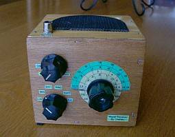
top view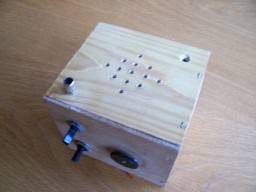 |
|
Inside
view 1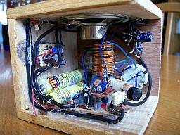 |
Inside
view 2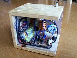 |
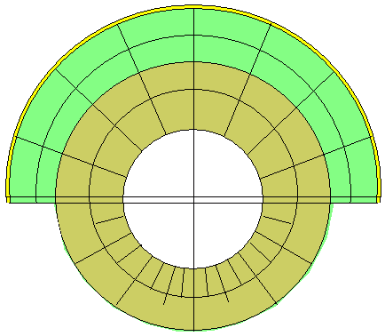
Dial scale (with the SW experimental scales included)
| More of my projects: 50 Mhz converter/receiver |
2)
RE-RX2MW: MW receiver based upon a ZN414
(retired, but can be replaced by a much better MK484 or TA7642)
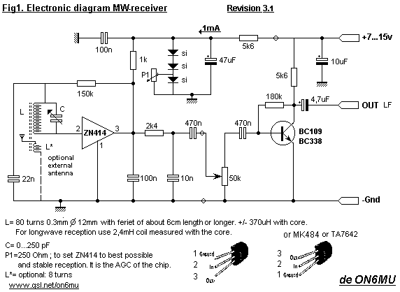
The MK484 easlily goes up to 3Mc and even somewhat beyond. Experiment with the RX1LM/HF coils on the top of this page!
AM radio is broadcast on
several frequency bands:
Long wave is 153–279 kHz; it is not available far into the
Western Hemisphere, and European 9 kHz channel spacing is
generally used (historically frequencies as high as 413 kHz were
used but currently there are no terrestrial LW broadcasters above
279 kHz).
Medium wave is 520–1,610 kHz. In the Americas (ITU region 2)
10 kHz spacing is used; elsewhere it is 9 kHz. ITU region 2 also
authorizes the Extended AM broadcast band between 1610 and 1710
kHz.
Short wave is 2.3–26.1MHz, divided into 15 broadcast bands.
Shortwave broadcasts generally use a narrow 5 kHz channel
spacing.
The allocation of these bands is governed by the ITU's Radio
Regulations and, on the national level, by each country's
telecommunications administration (the FCC in the U.S., for
example) subject to international agreements.
Long wave is used for radio broadcasting in Europe, Africa,
Oceania and parts of Asia (ITU regions 1 and 3). In the United
States and Canada, Bermuda and U.S. territories this band is
mainly reserved for aeronautics, though a small section of the
band could theoretically be used for microbroadcasting under the
United States Part 15 rules. Due to the propagation
characteristics of long wave signals, the frequencies are used
most effectively in latitudes north of 50°.
Medium wave is by far the most heavily used band for commercial
broadcasting. This is the "AM radio" that most people
are familiar with.
Short wave is used by audio services intended to be heard at
great distances from the transmitting station. The long range of
short wave broadcasts comes at the expense of lower audio
fidelity. The mode of propagation for short wave is different
(see high frequency). AM is used mostly by broadcast services
— other shortwave users may use a modified version of AM
such as SSB or an AM-compatible version of SSB such as SSB with
carrier reinserted. In many parts of the world short wave radio
also carries audible, encoded messages of unknown purpose from
numbers stations.
Frequencies between the broadcast bands are used for other forms
of radio communication, such as baby monitors, walkie talkies,
cordless telephones, radio control, "ham" radio, etc.
AM radio signals can be
severely disrupted in large urban centres by concrete bridges
with metal reinforcements, other Faraday cage structures, tall
buildings and sources of radio frequency interference (RFI) and
electrical noise, such as electrical motors, fluorescent lights,
traffic signals, or lightning. As a result, AM radio in many
countries has lost its dominance as a music broadcasting service,
and in many cities is now relegated to news, sports, religious
and talk radio stations although some musical genres —
particularly country, oldies, nostalgia and ethnic/world music
— survive on AM, especially in areas where FM frequencies
are in short supply or in thinly populated or mountainous areas
where FM coverage is poor.
Also more of my homebrew projects:
.ON6MU
Homebrew projects
.Radioamateur related projects
.ON6MU
Ham mods
.Modifications of transceivers
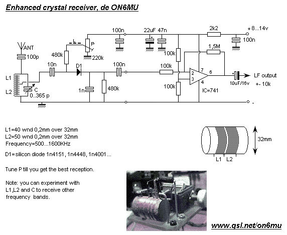
3) RE-RX1MW: Enhanced Crystal MW Receiver
3)
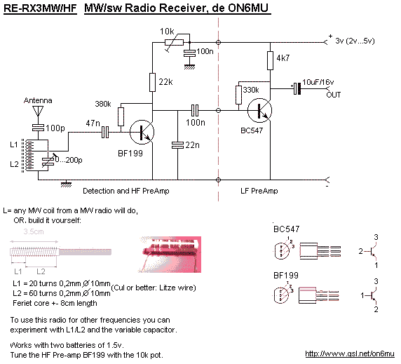
RE-RX3MW/HF: Enhanced Crystal MW/SW Receiver
(using one transistor for HF amplification and detection)
73"
![]()
Home
Radio kits velleman. Radio converter kits.
Kenwood, Yaesu receivers. Electronics schematics of radios.
Building kit of a home made crystal radio with transistor
components. Receiver commercial receiving antenna. shortwave
listening with receivers. Build your own shortwave receiver.
Performance not as a Kenwood or Yaesy receiver but so much more
fun to receive world wide signals. Not using integrated circuits.
Circuits integrated components of electronical contents. Antenna
longwire for shortwave reception.