HF/6M Antenna Tuner Preselector and Antenna Switcher
RE-AT1HF6
By Guy, de ON6MU
revision 4
![]()
HF/6M
Antenna Tuner Preselector and Antenna Switcher
RE-AT1HF6
By Guy, de ON6MU
revision 4
RE-AT1HF6 Schematic fig1
Parts list
alu box of 200mm X 130mm X 70mm
3 female PL 259 chassis
Analog Meter (as sensitive as possible and calibrate the scale with a good SWR meter)
C1 = variable capacitor of +/- 500 pF (air spaced)(1kv). C1 needs to be isolated from the ground!
C2 = variable capacitor +/- 280pF (air spaced)
C3,C4 = 10nF
C5 = 22nF
C6 = 470pF 500v (ideal is to use the same capacity as C1)
S1 = 7 pos. switch
S2 = mini toggle switch
S3 = solid 380v/10A toggle switch
P1 = 50k log variable resistor
D1, D2 = 2 germanium diodes AA15,AA109 etc.
D3 = any si diode
R1, R2 = 50 Ohm (2 x 1/4watt 100 Ohm parallel)
R3 = 1k8 1watt carbon (metal film or any type of non-inductive resistor)
L1 = 1,5mm insulated
copper wire, 30 turns close together, 19mm outside
diameter (16mm inside)
taps at 14, 9 and 7
L2 = 1,5mm insulated
copper wire, 5 turns with 1mm space, 19mm outside
diameter (16mm inside)
tap at turn 3
L3 = 1 mm insulated copper wire, 4 turns no space, 9mm outside diameter (7mm inside)
L4 = RG-58 coax wound around a 8 cm long carbon rod and fixed with tape
L0 & L0' = 1,5
turns approx. 6 cm as long as the centre part L0"
which is 1 mm separated.
you also can use self-adhesive copper tape instead of
wire or a toroid.
L0" = 6 cm long
copper wire (or copper line of 5 mm wide if you use a
PCB)
(L0, L0' and L0" makes out the SWR meter which is
laid out as in the schematic fig1)
L0 and L0' are acting as directional couplers. D1 &
D2 as envelope detectors.
Specifications
shortwave preselector tuner lets you boost your favorite stations while rejecting images, intermod and other phantom signals on your shortwave receiver/transceiver.
frequency range:
1Mc...52Mc
160m band and lower depending on the mismatch of the
antenna used and/or maximum inductance. Experimenting
with the coils and caps can be desirable.
150 Watt +-
switchable between two antenna's
shoke antenna output
band-pass type tuner (also functions as a L-type harmonic filter)
pre-selector
SWR meter (if needed, else you can simply leave it out HI)
By-pass switch
Revision 2 notes:
improved SWR bridge
R3: to drain any possible static build-up on your antenna
Revision 3 notes:
L3 added and last of L1 tap changed to allow tuning up to 52MHz!
L1 changed
(was at 9, 9, 9 and 4) for better bandspread and higher
top frequency range
L2 (was 1mm, 10 turns close together, 18mm outside
diameter) removed in revision 3 (click on the link for revision
2).
Choke antenna
output added to prevent HF-currents on the transmission
cables (to improve immunity when using badly tuned
antenna's)
Can be used on good antenna's too of course.
Revision 4 notes:
Added extra capacitor for the lowest frequencies, hence an additional setting (switch has to have 7 positions)
Main coil (L1 + L2) better bandspread and additional inductance for the lower bands
by-pass switch (use tuner or not)
added diode to meter to protect the meter for voltages over 0,6v
P1 is now 50k (experimentiation can be
needed according to the sensitivity of the meter used)
Notes: remember that you can always experiment with inductance (L1, L2, L3) to best suit your specific needs.
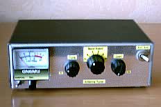
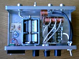
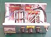
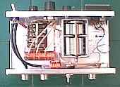
Pictures
original prototype
revision 2
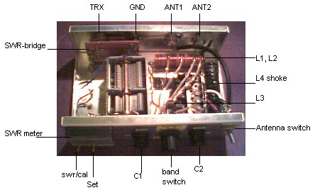
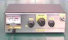
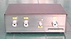
All revisions
This is how Herman PA3EHZ
made the tuner:


click images to enlarge
Thanks Herman for the pics!
If you elect to use an antenna tuner, it is extremely important that you understand exactly how to use tuners and what they can and cannot do. A few watts of RF can easily become lost in an incorrectly adjusted antenna matching device. I cannot overemphasize the priority of a clean, efficient connection of the amplifier output to a resonant antenna.
Here is another tuner based on this design, but smaller for portable useage:
Don't
forget to check these out:
.ON6MU
Homebrew projects
.Radioamateur related projects
.ON6MU
Ham mods
.Modifications of transceivers
73"