Allmode RF Power Amplifier
for the HF 15 and 17 meterband (21Mc/18Mc)
RE-PA10HF17 and RE-PA10HF17
revision 1.3
By Guy, de ON6MU
![]()
Allmode RF Power
Amplifier
for the HF 15 and 17 meterband (21Mc/18Mc)
RE-PA10HF17 and RE-PA10HF17
revision
1.3
By Guy, de ON6MU
About the 15- and 17-meterband HF amplifiers
This project and your efforts will provide you with a 0.55...2 watt input to easily 8 watt output. The two linear amplifiers are ment for use with QRP SSB/CW/FM/AM transmitters on the amateur bands 15 and 17 meters can be powered from a 12 volt DC supply. The design is a good balance between output power, physical size. The completed amplifier will reward the builder with a clean, more powerful output signal for a QRP rig when radio conditions become marginal. It has a RF-sensing circuit (Q2) wich allows the amplifier to switch on automatically when transmitting. This project uses a "classic" RF transistor. MOSFET power amplifiers are discussed and build in the near future on this website.
Bias
Power amplifiers used in base stations require biasing for
proper RF performance. BIAS has be applied to Q1 to have clean
proper and correct SSB modulation using this amplifier. Set P1 so
+/- 35 mA current flows through Q1. Depending on the type of
transistor this can vary somewhat, although you should never
exceed 60mA! You don't need SSB? Read next part.
CW/AM/FM only
If you only want to amplify AM/FM/CW/FSK type of modulation
(NOT SSB) then you can leave out the BIAS section for Q1 (between
b1 and b2 in the schematic). You simply connect connection b2 to
the ground, hence leaving out the somewhat critical setting of
the correct BIAS for operating clean SSB.
Modulation modes
If using the schematic as displayed below and so also using
Q1 BIAS, you can amplify any type of RF generated modulation
waves.
Filter
RF purity and harmonic suppression is done here. Also allowing
the transistor to be coupled to the antenna system through
antenna impedance matching circuitry (C14). Care is taken at this
stage so that no harmonic frequency is generated which will cause
interference in adjacent band (splatter) on other bands. This
4-element L-type narrow bandpass filter circuit and a 3 element
low-pass PII filter for the desired frequency cleans out any
remaining harmonic signals very efficiently.
Housing/shielding
The whole circuit needs to be mounted in an
all-metal/aluminum case. If you're unable to obtain an all-metal
case, then use a roll of self-sticking aluminum tape (available
from your hardware store) or PVC box painted with graphite paint.
Just make sure that all individual pieces of aluminum-tape (or
the graphite paint) are conducting with each other. Works fine.
RF-sensing
The basic principle of RF-sensing using a relay is clearly
drawn in the schematic and pretty much self explaining. Q2
(BC338, 2N2222) will conduct when RF energy is applied at the
input of the amp (and so also via C18, D3, D5 biasing the base of
Q2) hence powering up a RF capable relay. This relay switches
between RX and TX with amp. When no Vcc is applied to our
amplifier (and so Q2 too) no amplification is done. The input is
simply re-directed directly to the output (as if your transceiver
is connected without an amp). The RF sensing circuit is sensitive
enough to react on .5 watt easily.
To allow the amplifier in SSB-modulation some extended PTT
time-on the RF-sensing unit (Q2->relay) has to be increased.
This is done by closing S1 (SSB/FM) and so C20 adds the needed
"breathing" time. In FM/CW/AM/FSK modes a carrier is
present and extended PTT time-on of the amplifier isn't needed,
hence can be short.
Important: timing can vary on the type of relay used (Ohms
resistance value of the relay coil), so often experimentation of
C19 & C20 is needed.
An error in the schematic previous to rev. 1.3 connected the
input of the rf-sensing circuit wrongly to C10, instead of the
input PL259 connector IN.
Important: Everything will be within specs if you use RY5W relay,
but timing (the "breathing time") can vary on the type
of relay used (Ohms resistance value of the relay coil), hence
experimentation of C31 is needed.
Note:
Although this example of RF-sensing isn't the Worlds most best
sollution, it is pretty easy for beginners though. Better would
be to drive t2 from your transceiver (amp drive) as this will
switch at the very moment of PTT.
RE-PA10HF17: 17-meterband Amplifier settings
First set C12 and
C14 to the middle and centre pin of P1 to the ground. After
carefully mounting all parts and using as short as possible
connections between the parts, gently add voltage to the
amplifier while checking the current. The only current you should
see is a the liddle idle current of Q1 (and LED D6 if connected).
Increase the voltage to 12 volts. Check current again. It should
(at this stage) be lower then +/- 20mA.
Now gently turn P1 till you get approx. 35 mA. Do not forget to
mount Q1 on a heat sink isolated electrically from the
transistor.
So far so good? Now we check if the (Q2) RF-sensing circuit is
working properly. Connect a proper dummy load and a power meter
to the output of the amp. Remove any connectors from your power
supply and temporary disconnect the collector from the VCC.
Connect your transceiver to the input. Be sure you set your
tranceiver's power to minimum (never more then 3 watts) and you
set your transceiver to 18.100Mc in CW/FM. Key your transceiver
and if all goes well the Relay should power up and you should see
the current rise and your power meter should already show an
amplification of the RF input power.
Still all working as planned? Excellent! Now carefully turn C12
till you get maximum output power (whilest checking the input SWR
on your transceiver or SWR meter). And finally tune C14 to
maximum power. If needed re-tune C12 and C14 till you reached the
maximum. Current should be around 1.2 Amp +/- (depending on the
voltage and input power).
Parts list 17-meterband power amplifier
Q1 2SC1969
(only Mitsubishi type!!), ERF-2030, 2SC1173, 2SC1944,
2SC2075
(with proper heatsink isolated from the transistor)
Note: There are reports I've read on various web sites
about counterfeit components especially RF transistors,
so be careful in buying huge lots. For example: I know
that the 2sc2075 marked with a T works while others not?!
Q2 BC338, BC337, 2N2222
C1 1uF/25v
C2 22nF
C3 10nF
C4 560pF
C5 22uF/25v
C6 47nF
C7 100uF/25v
C8 1nF
C9 100nF
C10 68pF
C11 180pF
(Stan 9H1LO
reported using a 270pF instead of 120pF (rev1.2c 180pF)
prevented the amp from oscillating in 24mc, probably do
to differences in transistors and PCB)
(Peter DL6NL reported using a 200pF which allowed 1:1
SWR)
C12 6...40pF set at half position and tune to max power and best input SWR
C13 68pF
C14 6...40pF set at half position and tune to max power on 50 Ohm dummyload
C15 120pF
C16 47pF
C17 180pF
C18 10pF
C19 2.2uF/25v
C20 68uF/25v
C21 100nF
R1 1k5 (revision 1.2)
R3 1k5
R4 1k
P1 5k (revision 1.2) pot. to set BIAS for correct SSB operation +/- [email protected]
D1 1N4148 (revision 1.2)
D2 1A si diode 1N4001, 1N4005
D3,D4,D5 1N4148
D6 LED
Re = 12volt relay with silver plated contacts and low RF capacitance with 2times 3pole switch: RY12W-K
L1 = 1mm Cul (insulated copper wire), 7 turns close together, 7mm inside diameter
L2 = 0.6mm Cul (insulated copper wire), 14 turns 0.5mm space, 7mm inside diameter
L3 = 1mm Cul (insulated copper wire), 11 turns close together, 10mm inside diameter
L4 = 1mm Cul (insulated copper wire), 5 turns close together, 10mm inside diameter
Ls = 470 1/2 watt carbon, 0,2 Cul turned 3 times over the entire length of the resistor
Ferrite bead 3 turns wire inside
S1 switch open = AM/CW/FM/PSK/PKT, switch closed = SSB
Ls
Note:
Always use a dummy load for testing and adjusting the
amplifier!!!
Specifications RE-PA10HF17
Peak Frequency range: 18Mc...18.5Mc
Output RF
power: at
least 8W @ 13.8v - 11W@16v
power measured at maximum modulation depth
All modulation modes
Adjustable output impedance to 50 Ohms
Adjustable input impedance to 50 Ohms
High efficient band-pass type harmonic L-filter + lowpass PII filter
PII-filter at input
Usable voltages: Vcc 10 - 18 volts
Average current I: +/- 1A @ 14 v
RF-sensing
VSWR overload resistant (not infinite)
Can be used without complex BIAS if only needed for CW/AM/FM/FSK type modulation

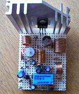
How Peter DL6NL made it!
Click image to enlarge
RF Power transistors:
2SC1969/ERF-2030
Features:
Absolute Maximum Ratings: (TC = +25°C unless otherwise specified)
| Collector-Emitter Voltage (RBE = Infinity), VCEO | 25V |
| Collector-Base Voltage, VCBO | 60V |
| Emitter-Base Voltage, VEBO | 5V |
| Collector Current, IC | 6A |
| Collector Power Dissipation (TA = +25°C), PD | 1.7W |
| Collector Power Dissipation (TC = +50°C), PD | 20W |
| Operating Junction Temperature, TJ | +150°C |
| Storage Temperature Range, Tstg | -55° to +150°C |
| Thermal Resistance, Junction-to-Case, RthJC | 6.25°C/W |
| Thermal Resistance, Junction-to-Ambient, RthJA | 73.5°C/W |
Electrical Characteristics: (TC = +25°C unless otherwise specified)
| Parameter | Symbol | Test Conditions | Min | Typ | Max | Unit |
| Collector-Base Breakdown Voltage | V(BR)CBO | IC = 1mA, IE = 0 | 60 | - | - | V |
| Collector-Emitter Breakdown Voltage | V(BR)CEO | IC = 10mA, RBE = Infinity | 25 | - | - | V |
| Emitter-Base Breakdown Voltage | V(BR)EBO | IE = 5mA, IC = 0 | 5 | - | - | V |
| Collector Cutoff Current | ICBO | VCB = 30V IE = 0 | - | - | 100 | µA |
| Emitter Cutoff Current | IEBO | VEB = 4V, IC = 0 | - | - | 100 | µA |
| DC Forward Current Gain | hFE | VCE = 12V, IC = 10mA, Note 1 | 10 | 50 | 180 | |
| Power Output | PO | VCC = 12V, Pin = 1W, f = 27MHz | 16 | 18 | - | W |
| Collector Efficiency | 60 | 70 | - | % |
Note 1. Pulse test: Pulse Width = 150µs, Duty Cycle = 5%.
ERF-2030 Features...
1/ The ERF-2030 is a 25 watt* transistor - therefore, it
is not just a replacement part, but also an UPGRADE to the old
Mitsubishi part.
2/ The ERF-2030 is NOT an "electrical drop
in replacement" for the 2SC2166, 2SC1969 and 2SC2312.
However, circuit modifications on most radio's are minimal and
documentation is readily available for FREE.
3/The ERF-2030 is a "mechanical drop in
replacement" for the 2SC2166, 2SC1969 and 2SC2312. This
means that the The ERF-2030 features a TO-220 package with the
SAME pinout configuration as the 2SC2166, 2SC1969 and 2SC2312.
Therefore NO mechanical modifications to the ERF-2030 are
necessary for most installations
Allmode RF Power
Amplifier for the 15 meterband (21Mc)
RE-PA10HF15
By Guy, de ON6MU
About the 15-meter band HF amplifier RE-PA10HF15
All is already explained above (17-meter band amplifier): Read it here
15-meterband Amplifier settings
First set C12 and
C14 to the middle and centre pin of P1 to the ground. After
carefully mounting all parts and using as short as possible
connections between the parts, gently add voltage to the
amplifier while checking the current. The only current you should
see is a the liddle idle current of Q1 (and LED D6 if connected).
Increase the voltage to 12 volts. Check current again. It should
(at this stage) be lower then +/- 20mA.
Now gently turn P1 till you get approx. 35 mA. Do not forget to
mount Q1 on a heat sink isolated but electrically from the
transistor.
So far so good? Now we check if the RF-sensing circuit is working
properly. Connect a proper dummy load and a power meter to the
output of the amp. Remove any connectors from your power supply
and temporary disconnect the collector from the VCC. Connect your
transceiver to the input. Be sure you set your tranceiver's power
to minimum (never more then 3 watts) and you set your transceiver
to 21.200Mc in CW/FM. Key your transceiver and if all goes well
the Relay should power up and you should see the current rise and
your power meter should already show an amplification of the RF
input power.
Still all working as planned? Excellent! Now carefully turn C12
till you get maximum output power (whilest checking the input SWR
on your transceiver or SWR meter). And finally tune C14 to
maximum power. If needed re-tune C12 and C14 till you reached the
maximum. Current should be around 1.2 Amp +/- (depending on the
voltage and input power).
Parts list 15-meterband power amplifier RE-PA10HF15
Q1 2SC1969
(only Mitsubishi type!!), 2SC1173, 2SC1944
(with proper heatsink isolated from the transistor)
Q2 BC338, 2N2222
C1 1uF/25v
C2 22nF
C3 10nF
C4 560pF
C5 22uF/25v
C6 47nF
C7 100uF/25v
C8 1nF
C9 100nF
C10 68pF
C11 100pF (If amp oscillates in higher frequencies do to transistor deviations or PCB coupling, try 180pF)
C12 6...40pF set at half position and tune to max power and best input SWR
C13 56pF
C14 6...40pF set at half position and tune to max power on 50 Ohm dummyload
C15 100pF
C16 47pF
C17 150pF
C18 8pF
C19 2.2uF/25v
C20 68uF/25v
C21 100nF
R1 1k5 (revision 1.2)
R3 1k5
R4 1k
P1 5k (revision 1.2) pot. to set BIAS for correct SSB operation +/- [email protected]
D1 1N4148 (revision 1.2)
D2 1A si diode 1N4001, 1N4005
D3,D4,D5 1N4148
D6 LED
Re = 12volt relay with silver plated contacts and low RF capacitance with 2times 3pole switch: RY12W-K
L1 = 1mm Cul (insulated copper wire), 6.5 turns close together, 7mm inside diameter
L2 = 0.6mm Cul (insulated copper wire), 12 turns 0.5mm space, 7mm inside diameter
L3 = 1mm Cul (insulated copper wire), 11 turns close together, 10mm inside diameter
L4 = 1mm Cul (insulated copper wire), 4.5 turns close together, 10mm inside diameter
Ls = 470 1/2 watt carbon, 0,2 Cul turned 3 times over the entire length of the resistor
Ferrite bead 3 turns wire inside
S1 switch open = AM/CW/FM/PSK/PKT, switch closed = SSB
Ls
Note:
Always use a dummy load for testing and adjusting the
amplifier!!!
Specifications
Peak Frequency range: 21Mc...21.5Mc
Output RF
power: at
least 8W @ 13.8v - 11W@16v
measured at maximum modulation depth
All modulation modes
Adjustable output impedance to 50 Ohms
Adjustable input impedance to 50 Ohms
High efficient band-pass type harmonic L-filter + lowpass PII filter
PII-filter at input
Usable voltages: Vcc 10 - 18 volts
Average current I: +/- 1A @ 14 v
RF-sensing
VSWR overload resistant (not infinite)
Can be used without complex BIAS if only needed for CW/AM/FM/FSK type modulation
Antenna's
It's important to
use a correct designed antenna according to band you would like
to operate, or at least use a good antenna tuner to match the
antenna (protecting your transmitter and proventing
harmonics/interference...). Several examples can be found on my
website and all across the Web. A dipole is always a good
alternative (total length = 150/freq - 5%).
The performance (distance relative to you RF power) of your
antenna is as importent (if not more) as the RF power you
transmit! A dummy load gives also a perfect 1:1 SWR, but you wont
get any farther then the street you live in HI. Finally,
athmospheric conditions (D-,E-,F-layers depending on the
frequency you're using) is equally important to be able to make
DX QSO's.
Related
Remember that transmitting and/or using an power levels higher then your local license permit is illegal without a valid radioamateur license!
Another related
project:1watt 10 meterband transmitter project