VHF Optimized Yagi Antenna for the 6-meterband (50 Mhz)
RE-A50Y3
By Guy, de ON6MU
![]()
VHF
Optimized Yagi Antenna for the 6-meterband (50 Mhz)
RE-A50Y3
By Guy, de ON6MU
Schematic fig1
Highlighted
Parts list for the long yagi antenna RE-A50Y3
2 meter long
alu/copper pipe/tube of +/- 20...28mm (square or round)
or if using portable, use 2 x 1 meter pipes/tubes fitted
together in the middle of the boom with a larger piece
that slides over. Same goes for the centre of the
elements.
6 pieces of 1
meter alu or copper tubing:
- 12...18 mm diameter
3 pieces of 2
meter long alu or copper tubing:
- 15...22 mm diameter
Gamma match: alu or copper tube of 250 mm of 8mm diameter
some cul wire (isolated wire, installation wire, etc.) of 4 mm copper diameter (+/- 6...7mm diameter with isolation)
some alu/copper plates to construct the strap holder for the gamma-match
1 female PL 259 chassis
some silicon, grease... to make the construction weather resistant.
several lengths of innox bolts or other non oxidating bolts
a bracket to mount the yagi to a boom
and a few
innox hose clamps
Note: there are many ways to
build your antenna and I'm sure some can come up with better
mechanical designs then described here although the design and
material used here is cheap and easy to find. Also, the diameters
of the tubing described here is not too critical.
Links of interest:

Gamma-match
When the dipole is
the driven element of a Yagi parasitic array, the impedance that
appears at the center of the driven element will usually be quite
different from that of the isolated dipole. The reason for this
is that the Yagi antenna is equivalent to a number of resonant
circuits tuned to different frequencies and coupled together. The
self-impedance of the parasitic elements and mutual impedance
between parasitic elements and driven element cause resistance
and reactance to be coupled into the driven element.
A gamma-match tube act's like a capacitor. The
"capacitor's" sole purpose, is to oppose unwanted
inductive reactance. It is a series-tuned LC circuit between the
coaxial cable's center conductor and the gamma's connection point
at the driven element hence getting a pure Ohms resistance. So, a
gamma match taps a point on one side of the center of the driven
element and connects the feedline to that point through a
capacitor. In this design a tube with a copper wire inside acts
as air-spaced capacitor. Another advantage is to allow the center
of the driven element to be directly grounded to the antenna's
boom, making driven element assembly easier and no static
build-up on the driver.
To tune the gamma-match to a desired frequency for best SWR you
will need to experiment with the placement of the strap on the
driver (feedpoint) and the position of the strap relative to the
feedpoint.
If you build the yagi antenna according to above specs, then you
should be pretty close (if not spot-on) to a ideal match.

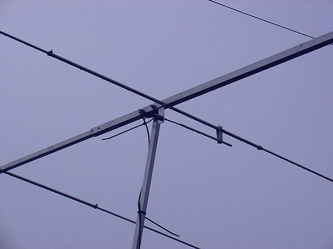
How Hernan, LW5DTZ did the Gamma-match
Specifications ON6MU 50 Mc wide-spaced yagi antenna RE-A50Y10
Total length 2 meters
Max width 2,95 meter
Peak centre frequency: 50,5 Mhz
Maximum bandwidth: 2...2,5 Mhz
Gain: 6,1 dBd
F/B ration: 25dB
Horizontal opening angle: 45°
Vertical opening angle: 55°
Maximum tunable frequency range: 49...54 MHz+-
impedance: 50 Ohms
Maximum power using the components described: 300 watt
DC grounded (no static buildup do to all elements being electrical/mechanical connect at the center. Of course the boom/tower/mast itself needs to be grounded too)
Solid air-spaced gamma-match design
If needed, it
can be disassembled into a very small bundle no longer
than the longest element being 1 meter.
Be sure to seal everything up to avoid moisture, corrosion etc...
| Today's specials: |
.ON6MU
Homebrew projects
.Radioamateur related projects
.ON6MU
Ham mods
.Modifications of transceivers
Please take a
look at my 50mc vertical antenna
Users Feedback
This
is how Greg, SP5LGN made my 50mc
long-yagi:
please click the images to enlarge
Take a visit to Greg, SP5LGN his website: http://www.sp5lgn.ampus.pl
Thanks
Greg for the photo's!!
---------------
********************************************************************
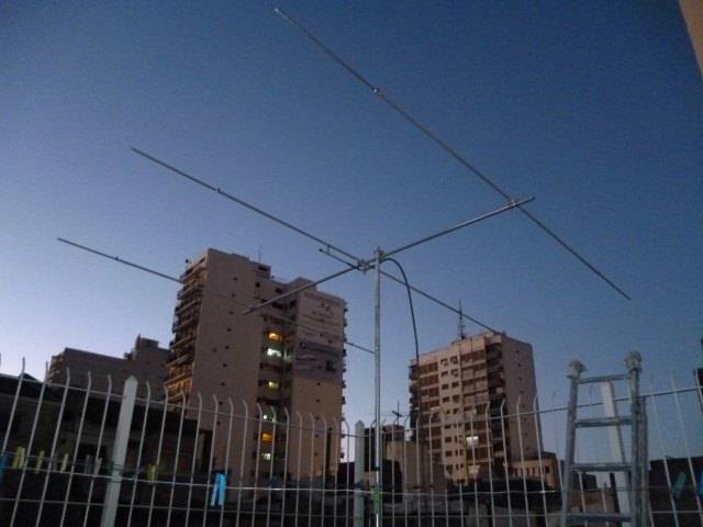
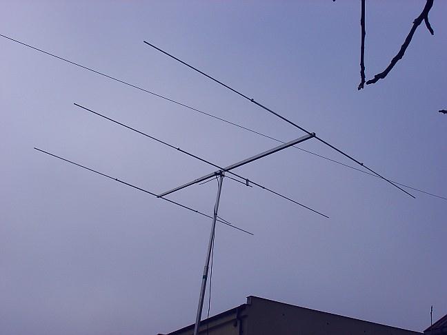
This is how Hernan,LW5TDZ made it:
Thanks
Hernan for the pictures!
---------------
********************************************************************
This is a webpage on how Eric KB3CNH made the antenna:
http://impbarn.blogspot.be/2016/10/amateur-radio-building-3-element-yagi.html
He needed
to shorten the driver element.
Nice webpage, great review!
---------------
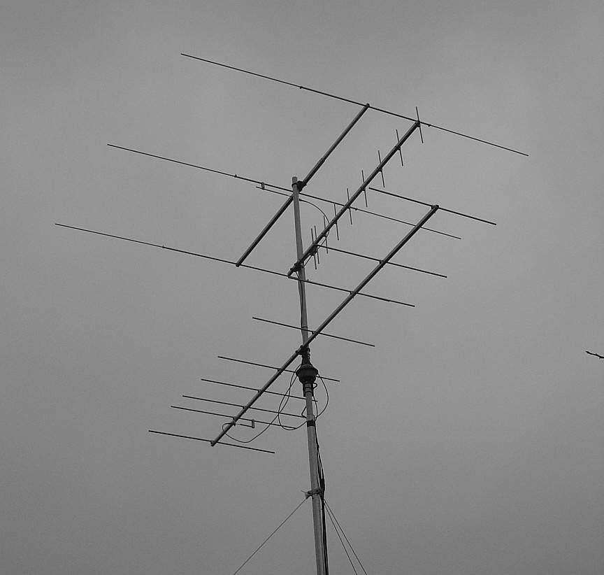
This
is how Kevin, VE7ZD made it:
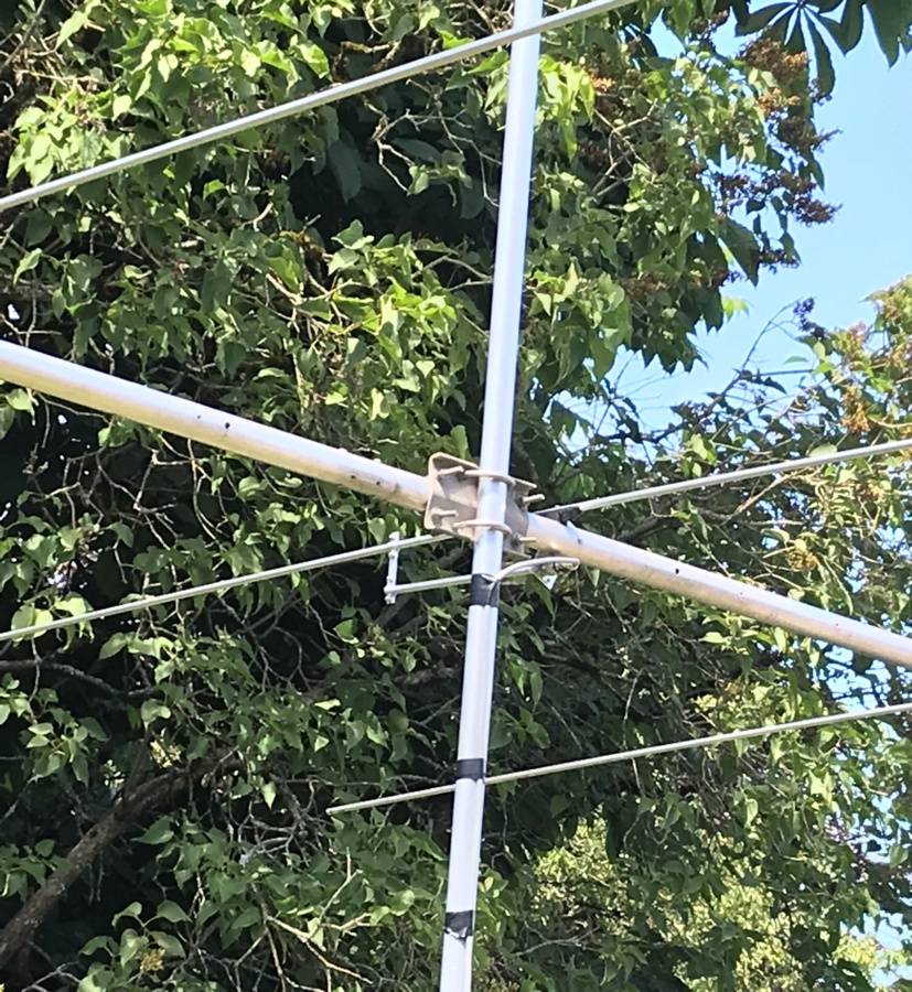
"
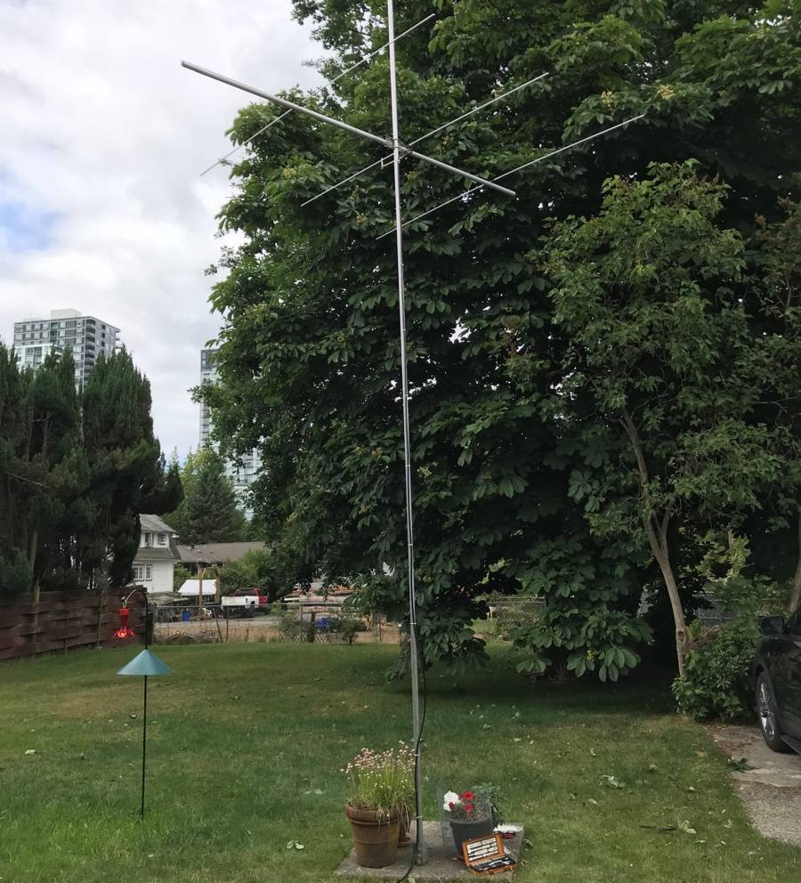
I built the antennas mostly out of surplus junk from my basement,
and it is working very well. I have it on a 6 metre pole in the
back yard, fed with about 20 metres of LMR400.
I am new to 6 metre work and the "step up" to a Yagi
from my mis-matched 20m dipole has made an amazing difference. I
am regularly hearing stations over 1600 km away, this without a
significant band opening.
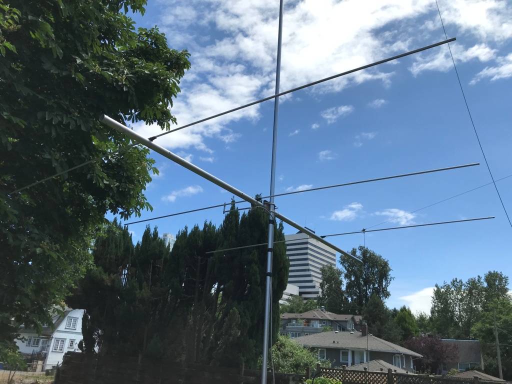
I used solid 9.5 mm aluminum rod for the elements and an old 38
mm aluminum boom from a retired 2m Yagi that I used for EME in
the 1980s.
My gamma match uses the centre conductor and foam dielectric from
an old length of RG8/U "foam" type cable.
Weatherproofing is critical as we get a high volume of rain here
on the west coast of Canada.
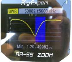
I also had to shorten the driven element. My resonant frequency
was too low so I cut off first 0.8, then 1.0, then 0.8 cm from
each side of the driven element. This brought the low SWR point
to 49.982 MHz.
I was aiming for 50.313 MHz for FT8 so I decided that this would
be good enough, as I thought that the SWR may change further than
the antenna gets moved from 1 m to 5 m elevation on the mast.
It was a good decision and the antenna at height is at SWR 1.1 to
1.
You’ll note that I used 9.5 mm solid aluminum rod for the
three elements, rather than tubing. This was cheaper than the
tubing and only a bit heavier.
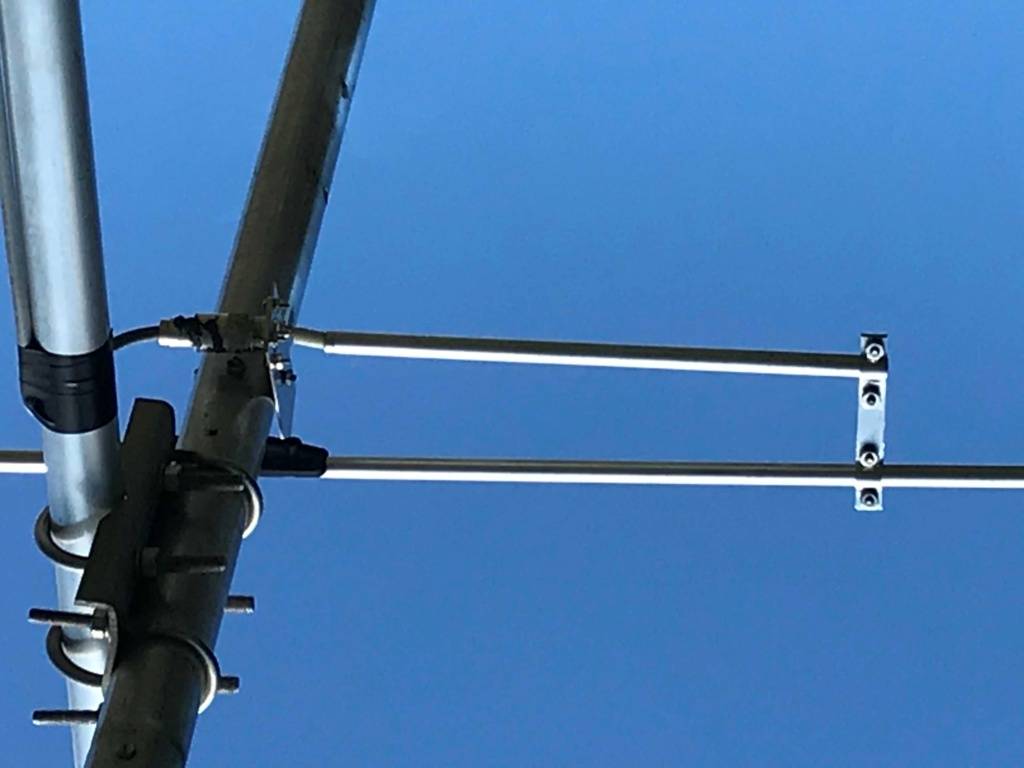
My antenna boom is a re-purposed 38 mm aluminum boom from an old
long-boom 2m EME Yagi. I was able to use the element supports
from that antenna as the solid rod was the correct size and fit
the holders perfectly.
My three elements are spaced off of the boom using Delrin
spacers, but ARE connected to the boom through stainless steel
hardware.
My gamma match was made of some old 3/8 “ tubing, and the
centre conductor was from spare RG8U “super flex foam”
coaxial cable.
I used the centre conductor and the white foam covering, just
removing the cable insulation and braid.
The antenna works very well so far, and I note good directivity
and gain in the chosen direction. I am using a manual rotation
method. The antenna is near the top of a 7m aluminum pole.
"
Thanks for the feedback and pictures, Kevin!
---------------
This is how Liviu YO4FNG made it:
https://www.qsl.net/yo4fng/50.htm
Thank
you for the information and details, Liviu!
---------------