|
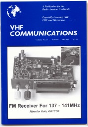
RX FM 137 - 141 MHz
highly
sensitive and selective superhetrodyne receiver
( SATELIT
METEOSAT 7, NOAA, METEOR, RESURS... )
[
Česká
verze ]
[ English version ]
[
Index ]
[
Down
Converter ] [  ]
]
Ing.
Miroslav GOLA
OK2UGS , QTH FRÝDEK - MÍSTEK
LOC: JN99EQ
[email protected]
Aktualizace
21. 04. 2003

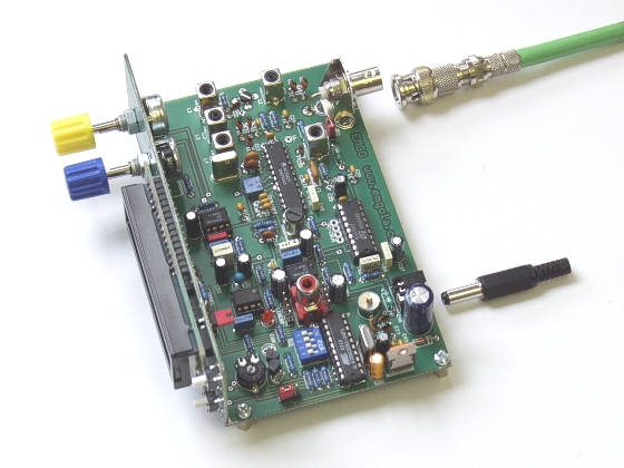
The
following text is meant for advanced hams and it describes assembly of FM
receiver for interesting waveband of 137 - 141 MHz, which is used for
transmission of images from space (views of the Earth from meteorological
satellites located at the distance of 850 km or 36000 km).

Receiver
technical data
| Frequency
Range : |
137
- 141 MHz |
| Frequency
Synthesizer Step: |
10,0
kHz or alternately 12,5 kHz |
| Input
Sensitivity: |
0,6uV
(rms-type) for 12dB SINAD |
| Intermediate
Frequency: |
10,7
MHz and 455 kHz |
| Tone
decoder/PLL
SE567: |
2400
Hz |
| Pass
band of the 2-st.IF filter: |
30
kHz/ - 3 dB or alternately 15 kHz |
| Power: |
DC
9 V (max.12 V) |
| Current
output: |
70
- 90 mA, according
to the loudness level setting |
| Power
Connector: |
3
mm (+ pole is
inside of the jack pin, - pole is on its surface!!!) |
| Automatic
Scanning: |
Yes
- 2400 Hz stop point - Squelch function
controlled by the uP |
| Noise
Gate ( SQUELCH ): |
Yes |
| Antenna
Connector: |
"1x
BNC" type |
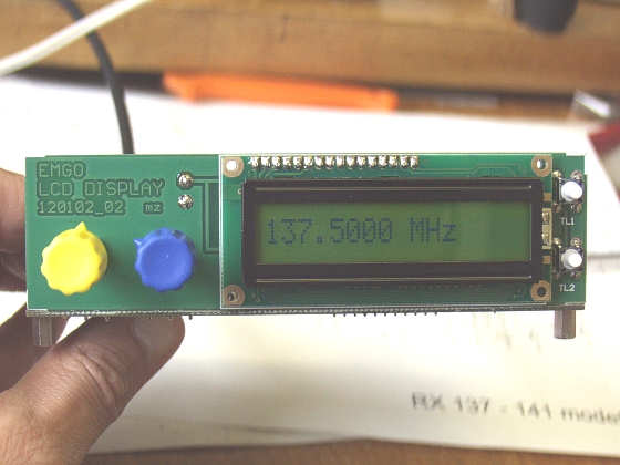
| Display: |
LCD
1 x 16 alpha - numerical
symbols |
| Connection
for Loud
speaker: |
(or
Headphones) external 8-25 Ohms, CINCH connectors |
| Connection
for PC: |
PIN
connectorsor cable from the computer sound card |
| Receiver
Size: |
225x200x70
mm |
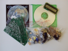
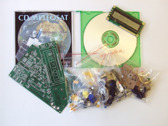
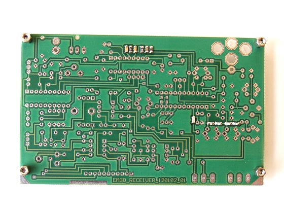
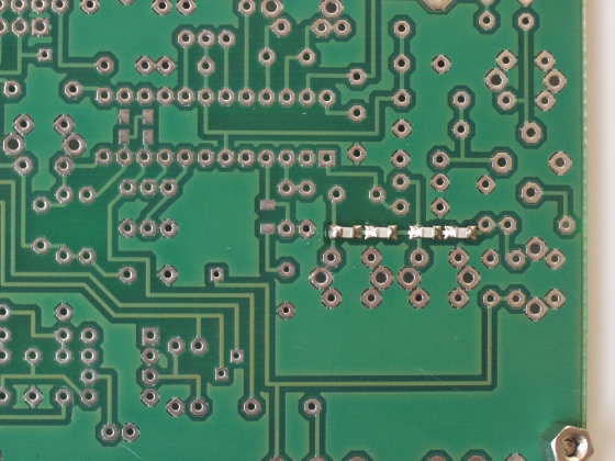
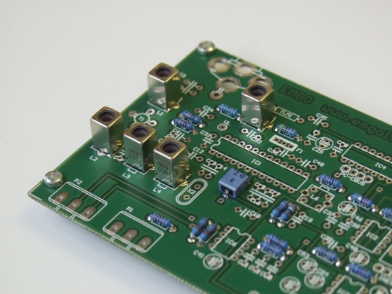
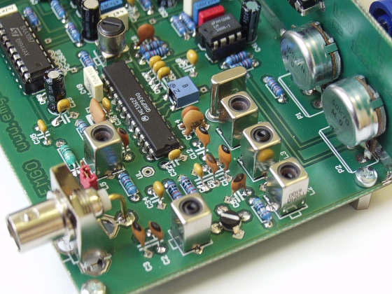
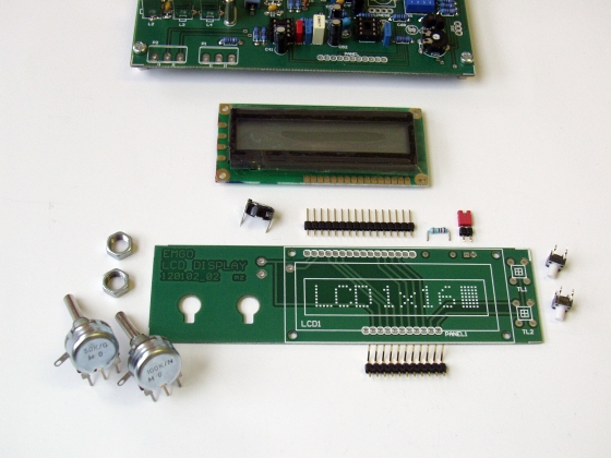
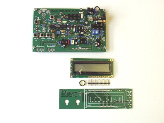
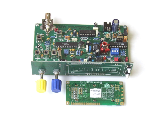
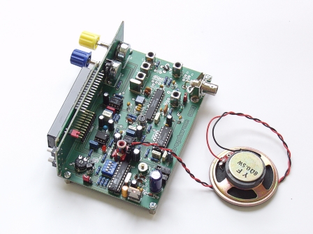
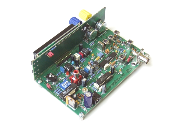
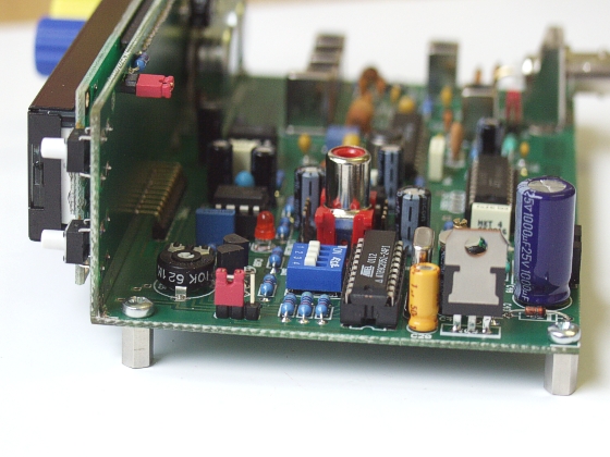
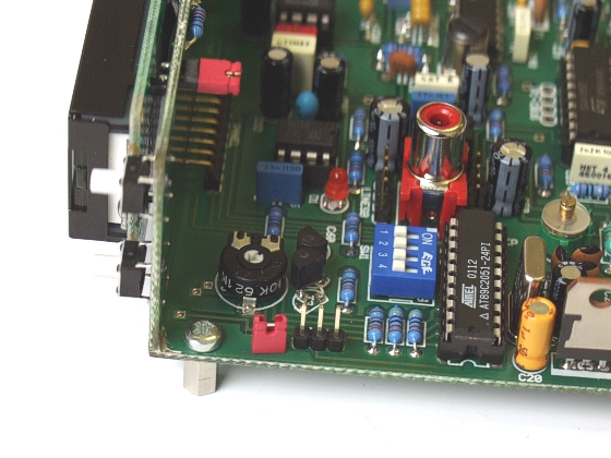
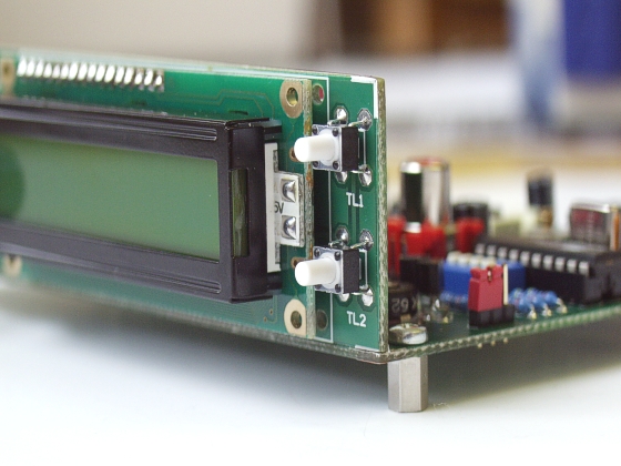
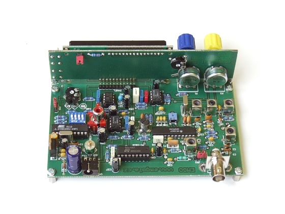
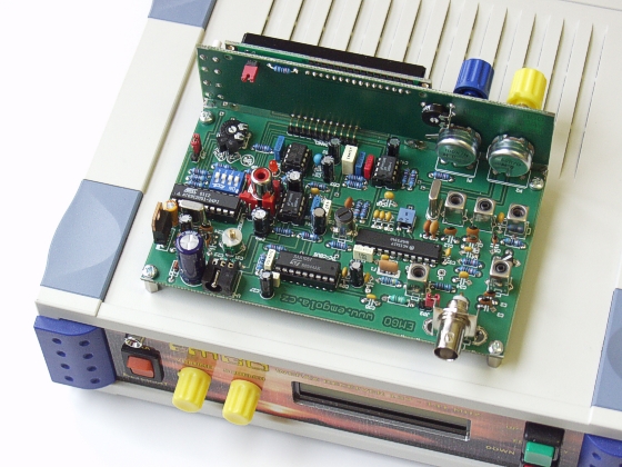
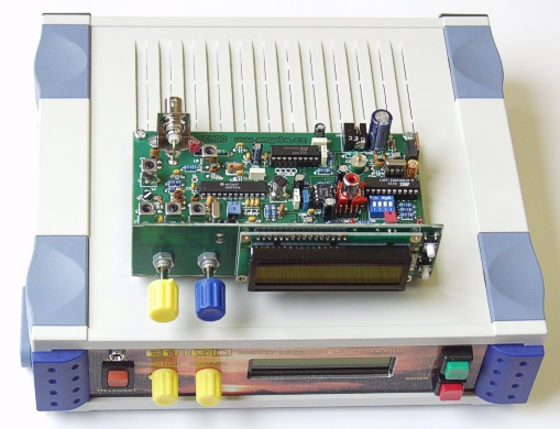
PHOTOGALLERY
|
|
Complete schematic you will find
here
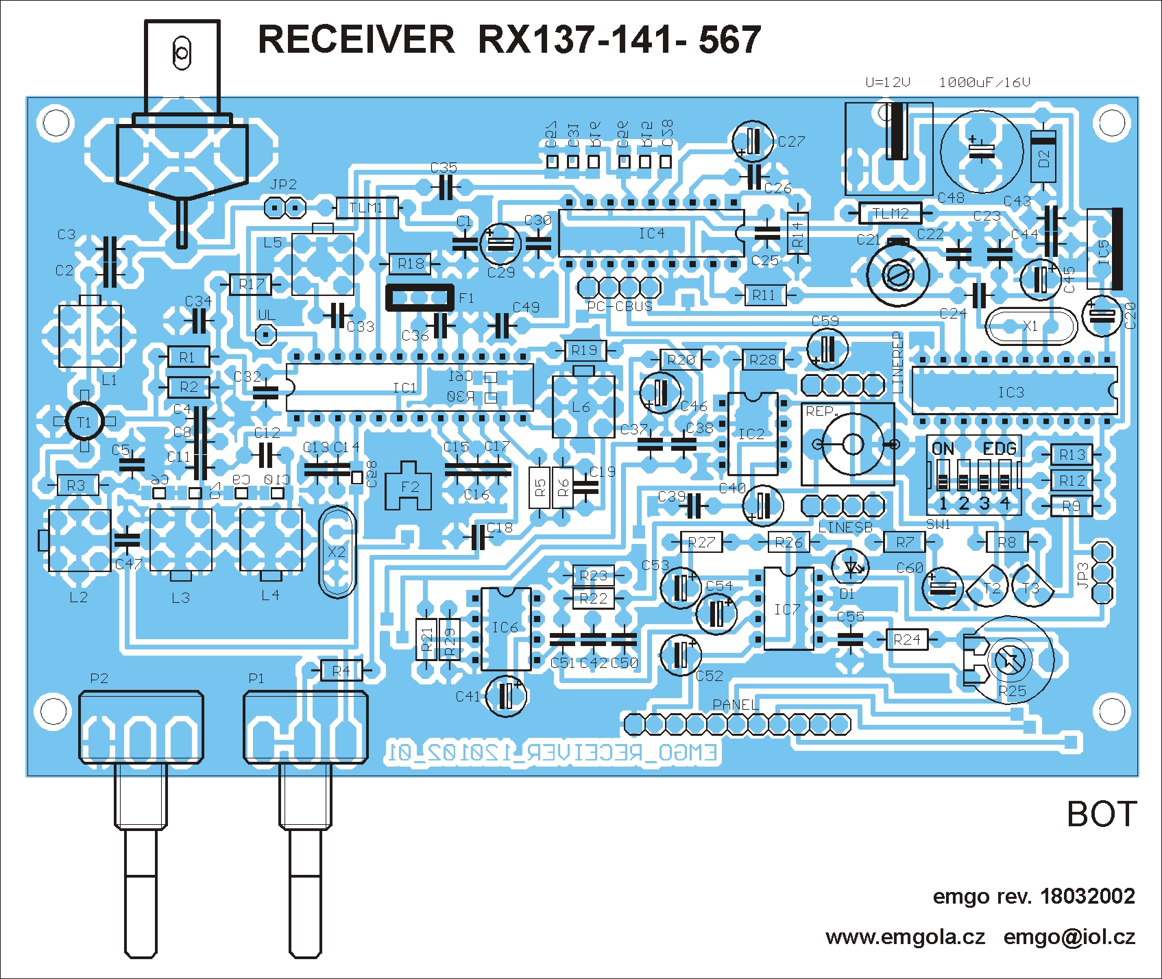
Components layout, top side
(bot PCB) here
Text here
[will issue in periodical VHF Communications 3Q/2002 ]

You
can order the kit with very detailed assembly instructions and with rich
photo documentation of details and complete unit on CD-ROM at our address:
Ing. Miroslav Gola -
EMGO, Areal VUHZ, a.s., Dobra 240, CZ-73951 Dobrá, Czech Republic
[email protected]
or [email protected]
You
can view current topical information on internet
site of the company EMGO...
|
|
Copyright
2000, 2001, 2002, 2003 [email protected]
|
|

