OH2GAQ
amateur radio station

HF Bands
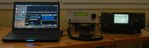
Tranceiver used is an Icom IC-7400, 100W SSB with an Icom AH-4 antenna tuner connected to a random length wire antenna (when connected !). You can guess I am not really so interested in the HF bands !
50 MHz
Same Icom IC-7400, 100W SSB, connected to a 3 element Yagi (fed with a gamma match), and rotated by a Create RC5-3 rotator.
144 MHz
Same Icom IC-7400, 100W SSB, connected to a 7 element Yagi (fed with a T match), and rotated by the Create RC5-3 rotator.

1.3 GHz and above common parts
All the bands 1.3 GHz and above are controlled by the OH2GAQ Microwave Transverter Controller (MTC V3, see the Projects pages). This provides a switcheable 28 MHz or 144 MHz IF, with a home-brew 144 MHz to 28 MHz (which can run in full duplex) converter whose 116 MHx LO is phase-locked to the frequency reference. A slightly modified Hermeslite version 2 DDC/DUC SDR provides the 28 to 30 MHz tuneable IF, and it can generate SSB, AM or FM. The MTC also contains Rb. frequency reference, sequencer and controller, R Pi 4 computer and touchscreen. Direct frequency readout is provided for all implemented microwave band TX and RX frequencies. It can be connected to up to 6 different half-duplex transverters and 1 full-duplex transverter.


1.3 GHz
The transverter used here is a collection of commercial kits and own designed parts, built into surplus base station mechanics. The basic transverter is the well-known DB6NT 1.3 GHz unit type MKU 13 G2. The RX side is either used as is, or preceded by a lo-noise pre-amp. The transmit side feeds a home-brew amp, using the Mitsubishi RA18H1213G module and a PCB designed by G6ALU, to provide up to 10W at 1.3 GHz. This is followed by a linear amp. using W6PQL's 150W kit, which provides over 150W PEP. A sequencer and protection unit controls the Tx/Rx switching, the power to the linear amps., and removes power and drive if SWR goes too high. It also provides a "health" signal to the MTC, so that any faults are noticed back in the shack. The whole microwave part can be mounted close to the antenna. The present antenna is a 26 element Yagi, driven element a folded dipole with half-wave balun. Antenna is designed using DL6WU wideband yagi design with dimensions given by VK5DJ's Yagi calculator, and constructed based on W6PQL's methodology.

10 GHz
The 10 GHz transverter is described in some detail on the Project pages. It uses a collection of home-brew modules and has been made to have a very clean local oscillator at 10.224 GHz, and a very well filtered output at 10.368, using a 5 pole waveguide filter. LO and image are greater than 70 db below the wanted signal. The LO is phaselocked to the MTC rubidium reference. A sequencer and protection unit controls Tx/Rx switching, the power to the linear amps., and removes power and drive if alarm conditions exist. It also provides a "health" signal to the MTC, so that any faults are noticed back in the shack. The transverter is built in a surplus microwave link cabinet, which connects by waveguide to the feedhorn of an offset fed 80 cm dish.


24 GHz
The 24GHz transverter LO uses the OH2GAQ Phase Locked Xtal Oscillator, operating at 124.500 MHz. It is phase locked to the Rb. controlled oscillator in the Microwave Transverter Controller. The oscillator is followed by a DB6NT multiplier chain kit, which produces about 30mW at 11.952 GHz for use as the LO. The LO is then fed to a DB6NT 24 GHz transverter kit, with a waveguide input/output port. A two cavity filter is used to select only the 24.048 GHz signal, suppress the image and provide additional LO suppression. A HP/Agilent co-axial switch is used to direct the mixer input/output to either the Rx. pre-amp (DB6NT 1.5 db NF, 25 db gain) or the Tx. PA thru a variable attenuator (0.5w output, about 50 db gain). The PA is followed by an isolator to protect the output stage. A waveguide switch is used to connect either the Rx. or Tx. port to a 30 cm. parabolic antenna. Local control and monitoring is done by the OH2GAQ Multipurpose Sequencer, which also feeds status to the MTC. The lock state of the 124.500 MHz oscillator is monitored, and selection of transmit mode is locked out until the oscillator is in lock. Also the position of the waveguide switch is monitored.