 |
There are 4 phases within one pulse cycle. You need for example (360/0.5)/4=180 pulses per rotation if 0.5deg resolution is wanted. |
Digital Position Encoders
Analog position indication systems using potentiometers are not exact enough for narrow beamwidth antennas (EME, SHF).
There are two different principles of digital encoders: INCREMENTAL and ABSOLUTE
1. INCREMENTAL ENCODER The current position is calculated by incrementing/decrementing a counter. The information for the counter is provided by a 2-phased pulse signal, with the phases seperated by 90deg from each other. So the direction (clw/ccw) of movement can be detected. The advantage is, that independent of the resolution (number of pulses per rotation), there are only two tracks necessary on the disk. But there is a big disadvantage: whenever the system ´forgets´ a pulse (too fast movement, not perfect tracks...) or the power supply is switched off, the position indication is wrong from that moment. In that case a reference mark must be passed to reset the counter.
|
There are 4 phases within one pulse cycle. You need for example (360/0.5)/4=180 pulses per rotation if 0.5deg resolution is wanted. |
2. ABSOLUTE ENCODER Each position is assigned to an unique bit combination. Therefore the correct position is indicated immediately after switching on the power supply. On the other hand, you now need 10 tracks for 0.5deg resolution . (2^10>360/0.5). For 0.1deg resolution 12bit (tracks) are necessary, with 900 bars on the track for the LSB.
Binary code is not suitable for an absolute encoder, because several bits can change at once when entering a new interval. (Example: 011 => 100). Using Gray-Code, only a single bit changes at all transitions. Gray-Excess-Code is similar, it is used for encoders with resolutions different from 1024, 2048, 4096 e.t.c. intervals. Conversion from Gray-(Excess-)Code to other codes, suitable for indication and/or controlling (Binary, BCD, ASCII...), is easily done with a microcontroller chip.
12 bit, absolute, single turn encoders will do the job for all radio amateur purposes,but professional encoders are quite expensive. Some of them have parallel output, some special output format, as for example the Serial Synchronous Interface (SSI). Incremental encoders are cheaper, but often they use exotic pulse numbers. For that case I have developed a pulse-converter. It can reduce the number of pulses per rotation to a number corresponding with 360*n.
Personally I prefer absolute encoders, and I successfully built 12bit encoders with 0.1deg resolution myself. But from my experience you need special mechanical skills and it is rather critical to adjust. For antennas with a mainlobe not narrower than 2deg ( 8m dish used on 23cm ), an encoder with 0.5deg resolution is good enough. So I developed an ´easy to build´ and ´no tune´ design which should be within everybodies possibilities.
Homemade 0.5deg resolution absoute position encoder
 |
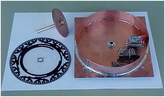
Figure 1 shows some
mechanical details.The brass disk (3) is soldered to the
axis (1). Both epoxy disks (6) and the transparent
Gray-Code foil between them (7) are squeezed together by
the upper clamp (4). The axis is passing through the
ground plane (5), made from epoxy and carrying the
printed circuit, via feedtrough (2) and held in position
by the lower clamp (4). The ground plane was made 150mm in diameter. The Gray-Code disk (120mm diameter) is made as follows: First step is printing the AutoCAD File abs05.dwg onto a transparent foil by a Laserprinter. You should use AutoCAD_R12 or a higher Version. If you have ACAD_Lt, download abs05lt.dwg instead. [Or for using it together with other CAD software abs05.dxf ]. The printout consists of two parts, mirrored to each other. Then cut out the two disks, and glue them together, so that the sensitive surface (toner) will be inside and cannot be scratched. |
 |
Figure 2: The measuring head is made of doublesided copperclad epoxy and two pieces of experimental board, with the holes drilled up to 1.5mm, so that the Infrared-LEDs and phototransistors can slip into the holes with their spherical head and are positioned ´in line´. As the distance between the holes is 1/10´´, each track on the Gray-Code disk has to be 2.54mm broad. So the 10 tracks fill 25.4mm. |
 |
The circuit, shown in Figure 3,
provides the digital output. Transparent part of the foil
disk means 0V at the connector pin, black part creates
5V. The output code is Gray-Excess. If another code is needed, it can be converted to Binary, BCD, serial ASCII by a 87C51 microcontroller. The ground plane of the encoder is used as a PC board carrying the 10k resistors and the CD4069 ICs. The 68R resistors were soldered to the measuring head. The supply current for the encoder is 30mA. |
| If only 1deg resolution is
needed, normally no adjustment is necessary. In the case you want 0.5deg resolution, it migth be that you have to adjust the position of the measuring head slightly by bending and resoldering. Also careful centering of the Gray-Code-Disk is recommended. |
Encoder partly assembled: Gray-Code-Disk on foil, axis with disks for clamping the foil, ground plane with measuring head and other components |
 |
|
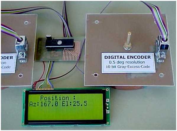
| A position indication
system can be designed as follows: The output of the encoders for azimuth and elevation is connected to ports of a 87C51 microcontroller, and there converted from Gray-Excess to Binary and then to BCD code. For indication you can directly connect a LCD-display to another port of the 87C51. Of course different solutions are possible as well. For example BCD output, serial output for prcocessing data with a PC. Meantime there are cheap absolute encoders on the market. Although I recommend using those for my EME_ANTENNA_CONTROLLER , it can be fun to build an encoder yourself. |
Test system: Az.+El. Encoder, 87C51 Microcontroller, LCD display |
 |