Mobile operation on HF bands requires high efficiency antenna systems
with a very rugged design and slim profile for low wind resistance. There
are many physical constraints when you are designing such an antenna:
-
mechanical lenght
-
bandwidt
-
multiband
-
power handling
-
mobile mounting
-
grounding
-
cost
-
diameter of coil
|
|
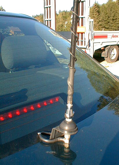
a 160cm whip with tapping:

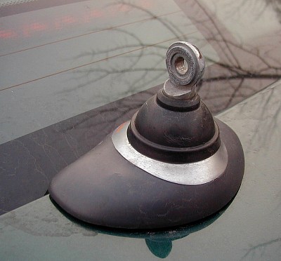
The simple mounting:
|
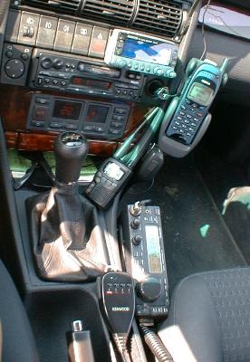
The following description should give you guidance on how to build
a mobile antenna for HF bands yourself, using a very cheap CB-mobile whip
antenna base.
-
buy a black CB mobile whip, abt. 160mm long, with helical wire and adjustable
top.
-
remove all black plastic cover from the glasfibre stick.
-
remove the helically wound copper band from glasfibre structure by cutting.
-
clean soldering points on bottom and top section of antenna.
-
use insulated copper wire of 0.7mm gauge
-
you will need about 10-15 meters of wire
-
use a electrical screwdriver for easy winding of wire on the glasfibre
stick
-
place a single layer of wire , very thight and narrow from bottom to top
section
-
solder the new wire onto previously cleaned supports on both ends of your
antenna.
-
mount the antenna on your car and check the resonant frequency, using an
MFJ antenna-analyser or your HF-transceiver with very low power.
-
the measured frequency with lowest SWR should be lower than the lowest
Hf-band you want to work in future mobile operation.(usually below 7Mhz)
-
now cut a piece of insulated wire longer than two times the mechanical
lenght of the antenna
-
solder this wire to the bottom of the antenna (together with the helical
coper wire)
-
run the wire in wide turns to the top of the antenna and solder it there
-
mount the antenna to your car and measure the resonant frequency for lowest
SWR. It should show low SWR above 29 Mhz, when the insulated wire is installed
and shortcuts the helically wound copper coil.
-
now disconnect the insulated wire from top and solder it to the middle
of the antenna. Make surre you scrap of existing insulation from copper
wire before soldering.
-
mount onto your car and measure the frequency of lowest SWR. Take notes
on a piece of paper and draw a graph (see example below)
-
You have now measured 3 different frequencies and so you schould be able
to identify all other tapping points for each band.
-
cover now each section from bottom to top with black shrink tube
and solder connectors for tappings.
-
After all your antenna should look like my example here and work fine on
all bands , even WARC or MARS.
-
maximum power is about 150 to 200 Watts.
-
if you add 110mm steel whip on top it works also on 75m and 80m bands
|
A simple and cheap mounting bracket from Diamond holds the antenna
in place, even at high speed.(180kmh)
Slim design is preferable in Europe and Japan, in order to avoid beeing
an attraction.
For operationa good grounding is important !
I am using the bracket you can see in the picture, mounted on the trunk
of an AUDI A6.
Nearly no dammage is donne to the car and cabel is entering the vehicle
through the rubber lid of car trunk. |
|
|
Here you can see a grphic of the principle of operation.
The concept is based on a helical coil that gets shortcut in some sections
for different bands. It is important to shorten from bottom to top, in
order to maintain good efficency and high Q and good radiation.Highest
current flows in the lower section of the antenna. No additional tuning
device is neccessary. |
Some cheap and easily available connectors can be used to perform the
tapping of the coil.
However, for band switching you have to stop the car.
Here is a table with reference lenghts:
|
MHZ Band distance
from feedpoint /cm
7
40 38
10
30 70
14,2 20
91
18,1 17
100
21,3 15
106
24,9 12
110
28,7 10
117
|
|
|
|
|

