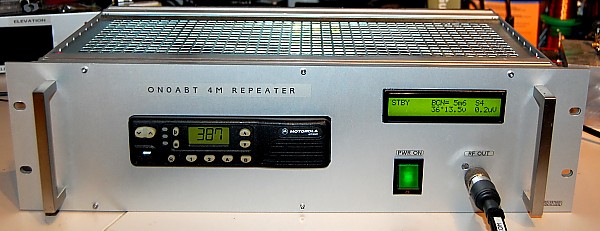
This project hereby presented is a complete HAM radio simplex 'smart' repeater, built around a Motorola GM-350/950, Arduino NANO board and a WINBOND audio recording integrated circuit.. The repeater was built to work on the 4m band, in order to promote activity and provide testing facility (by providing on-air S-reports)
Motivation :
On the 4m (70 MHz) band there is not enough bandwidth to work with split (uplink/downlink) frequency pair, because cavities are not able to separate / isolate signals this close. Therefore the concept of a simplex repeater – this works like a ‘parrot’, on a single frequency, records and plays back any signal sent with a valid CTCSS subtone for a duration up to 60 seconds.
Hardware :
-
Transceiver Motorola GM-350/950 : this transceiver offers the advantage to have all required signals / control lines available on it’s accessory connector. In particular, the fact that separate ‘channel busy’ and ‘CTCSS present’ signal are available is a big advantage, the presence of a RSSI (Receive Signal Strenght Indicator) is very welcome. Note : only the 128 channel model has an ACCESSORY PLUG !
-
Controller ARDUINO - NANO version (ATMEGA 328 based) – extremely compact and offers more I/O ports than standard type (UNO) with the advantage of being flashable by USB port on board.
-
Winbond ISD-2560 chip, providing up to 60 seconds record & playback in very high quality audio
-
Large LCD Display of 2x 24 characters, backlit (as alternative, a 2x 16 could be used, but you will lose the RSSI and Output Power data fields.
Information & data sheets :
-
Transceiver Motorola GM-350/950 : download my personalisation file (providing the I/O ports config I used). You will need the Motorola RSS software and an interface to load it in the rig (all info can be found on Internet, sorry I can't provide this, please don't ask for it... ) . See RSSI voltage info here (as measured on my RTX), see accessory plug connections info here
-
WINBOND ISD-2560 chip: leaflet (pdf 129k) / datasheet (380k) / circuit examples (1.4M) / extensive datasheet (8M)
-
LCD Display of 2x 24 char / HD44780 compatible: WINSTAR data sheet
System main features :
-
Self test at system start up (supply voltage, squelch, CTCSS, temperature, fan running, RF power/SWR, beacon ID)
-
GM350/950 is automatically powered-up when system power is applied and 'all safe'
-
3 operating statuses:
-
‘Stand-by’ or ‘Beaconing’ mode : Full repeater ID in CW at programmable intervals, with count-down timer displayed. Beacon sending is put on hold when frequency is not clear.
-
‘Repeater active’ mode :
-
Record mode : when signal with CTCSS is detected, goes into record mode. Software takes into account possible flutter and noise /‘Kerchunk’ spikes. When going into record mode, a short tone burst can be emitted, to signal other users on frequency that there is activity and recording has started. If recorded message is longer than 60 seconds (=Winbond chip limit), this is detected.
-
Playback mode : Plays back the recorded message, when the frequency is clear. If a message is too old, it is considered as ‘obsolete’ and will not be played back any more. A short beacon ID is transmitted in CW together with message played, at preset intervals. At the end of message played, the ‘S’ report of the recorded incoming signal is sent in CW. If the message was truncated , because too long, there is a warning in CW ('OVER')
-
After a timer has elapsed with no recording activity, mode returns to ‘STBY’ mode
-
-
-
In receive mode, signal strength is indicated on the display, both in µV and in S-points (up to S 9+40dB)
-
In transmit mode (Beacon and Play mode), the RF transmit power is shown. There is no measurement on reflected power (SWR), but a check is made if output power is within certain limits - therefore, if the SWR is high, transceiver is shut-off immediately.
-
Temperature of transceiver heat sink is continuously monitored (and displayed), when running hot the cooling fan is activated. When over temperature is detected , system is set in alarm and transceiver completely powered down
-
DC power supply voltage is continuously monitored (and displayed), when running in under- or overvoltage situation, system is put in error state, transceiver powered down
-
Extensive monitoring of all statuses on display (Carrier Squelch, CTCSS, operating mode, countdown of beacon transmit, count up / down of message length during record & playback, errors, fan running, … )
-
System automatic reboot (when not active, and no signals detected on frequency ) after 30 days (Roll-over of internal timers is covered), CW message played
-
System watchdogs :
-
On ARDUINO, 8 seconds ( reset of ATMEGA 328 controller)
-
On transceiver, 90 seconds maximum TX time (programmed in GM-350/950)
-
TO-DO list :
This is an on-going project , the sketch hereby presented is fully functional and debugged, but there are still some things on the 'nice to have' list !
-
Make some parameters (time related, repeater call sign & locator - now all hard coded) programmable by user and stored in EEPROM
-
.....
Pictures illustrating operation - project under construction:
Channel '375' corresponds with 70.375 MHz
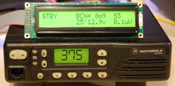
Stand-by mode. beacon will
be transmitted in 8min54sec. temperature 25°, supply voltage 12.9v. No
RF signal on-air
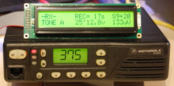
RX mode, CTCSS tone
detected, repeater Active, recorder running and counting up. RF signal
present S9+20dB
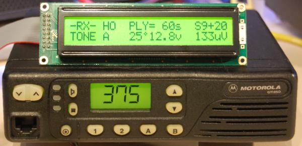
RX mode with recorder in
overtime, playback ready but put on Hold as still CTCSS on air
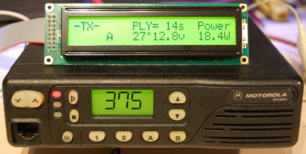
TX mode, repeater active,
message being played and counting down, output power 18,4W
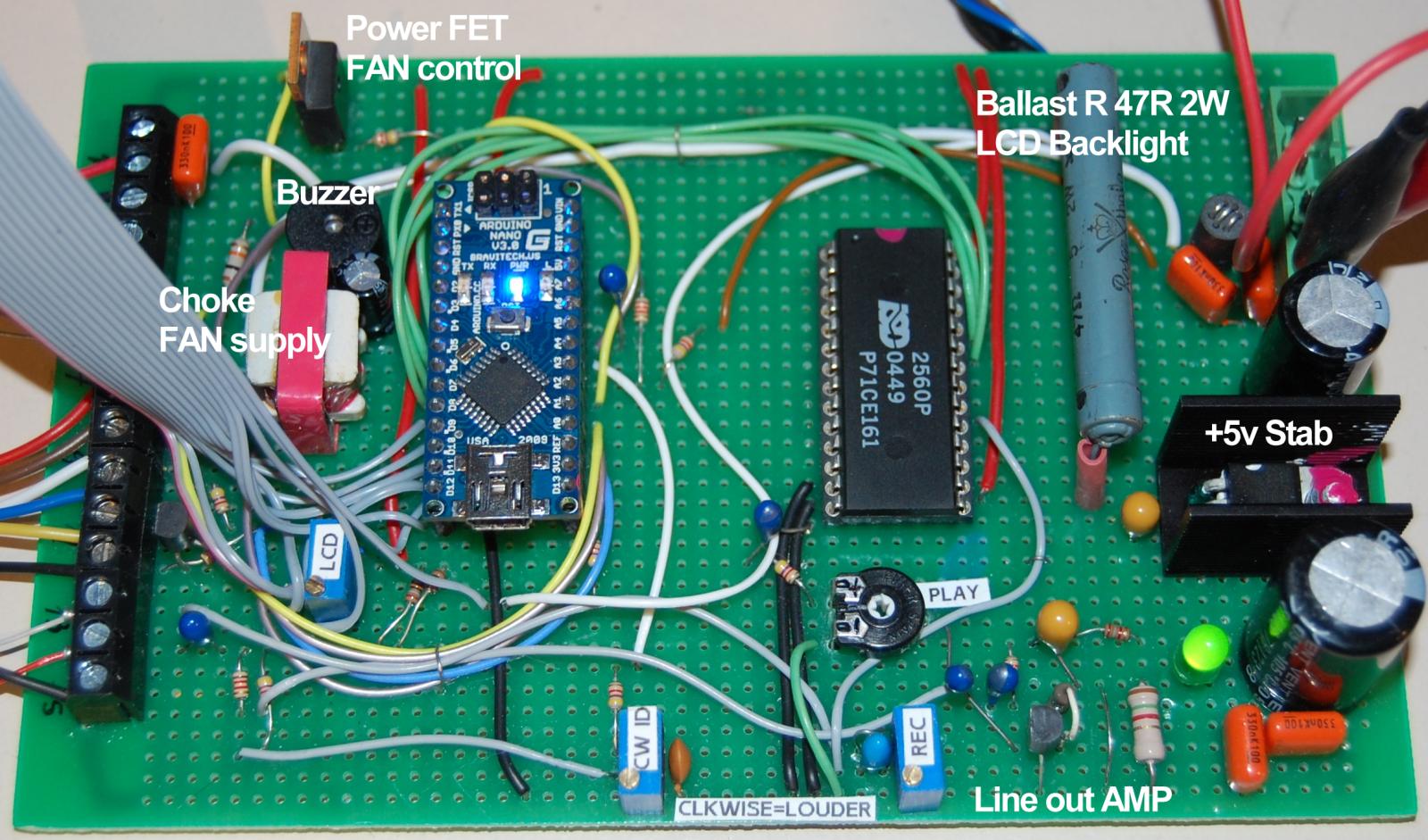
The complete circuit - click to zoom !
This is the sketch or download it here. It was compiled with IDE version 0022.- IMPORTANT : please use the same or you might get errors when compiling ! You still can download previous versions from ARDUINO website Feel free to contact me to check if an update is available...
// ******************************************** // *** SIMPLEX REPEATER CONTROLLER *** // *** by ON7EQ jan 2013 *** // ******************************************** #include <math.h> // required for NTC readout #include <LiquidCrystal.h> #include <avr/wdt.h> // Watchdog function // initialize the LCS library with the numbers of the interface pins /* * on typical 2x 16 LCD display * LCD RS pin to digital pin 7 * LCD Enable pin to digital pin 8 * LCD D4 pin to digital pin 9 * LCD D5 pin to digital pin 10 * LCD D6 pin to digital pin 11 * LCD D7 pin to digital pin 12 * LCD R/W pin to ground * Trimmer to LCD VO pin (pin 3) (contrast) */ LiquidCrystal lcd(7, 8, 9, 10, 11, 12); // build LCD specific characters 'degrees' byte degree [8] = { B00100, B01010, B00100, B00000, B00000, B00000, B00000, }; /////////////// Simple Arduino CW Beacon ////////////////// // Written by Mark VandeWettering K6HX // Email: [email protected] // // Thx Mark de ON7EQ ! // struct t_mtab { char c, pat; } ; struct t_mtab morsetab[] = { {'.', 106}, {',', 115}, {'?', 76}, {'/', 41}, {'A', 6}, {'B', 17}, {'C', 21}, {'D', 9}, {'E', 2}, {'F', 20}, {'G', 11}, {'H', 16}, {'I', 4}, {'J', 30}, {'K', 13}, {'L', 18}, {'M', 7}, {'N', 5}, {'O', 15}, {'P', 22}, {'Q', 27}, {'R', 10}, {'S', 8}, {'T', 3}, {'U', 12}, {'V', 24}, {'W', 14}, {'X', 25}, {'Y', 29}, {'Z', 19}, {'1', 62}, {'2', 60}, {'3', 56}, {'4', 48}, {'5', 32}, {'6', 33}, {'7', 35}, {'8', 39}, {'9', 47}, {'0', 63} } ; #define N_MORSE (sizeof(morsetab)/sizeof(morsetab[0])) #define CW_SPEED (18) #define DOTLEN (1200/CW_SPEED) #define DASHLEN (3.5*(1200/CW_SPEED)) // CW weight 3.5 / 1 ////////// end CW section //////////// // Temperature routine double Thermister(int RawADC) { double Temp; Temp = log(((10240000/RawADC) - 10000)); Temp = 1 / (0.001129148 + (0.000234125 + (0.0000000876741 * Temp * Temp ))* Temp ); Temp = Temp - 273.15; // Convert Kelvin to Celcius // Temp = (Temp * 9.0)/ 5.0 + 32.0; // Convert Celcius to Fahrenheit return Temp; } ///////////////// R E P E A T E R P A R A M E T E R S ////////////////////// #define RPT_call ("ON7EQ") // Call sign of the repeater #define RPT_ctcss ("79.7") // CTCSS tone / letter #define RPT_loc ("JO11OC") // Repeater QTH locator //////////////////////////////////////////////////////////////////////////////////// // ISD 2560 pins control #define ISD_mode_pin (2) // Pin for ISD mode control : Play = H / Record = L (ISD2560 pin 27 PDIP) #define ISD_PD_pin (4) // Pin for ISD PD/STOP/RESET : Normal = L / STOP or RESET (from EOM) = Pulse H (ISD2560 pin 24 PDIP) #define ISD_CE_pin (5) // Pin for ISD CE control : Normal = H / START = Pulse L (ISD2560 pin 23 PDIP) //PRM8020 - GM350 pins control #define PRM_PWR_pin (6) // Pin for enabling DC power to rig : Power on = H / power off = L (controlling power FET) #define PRM_PTT_pin (13) // Pin for PTT control : TX = H / RX = L - connect via 'open collector' transistor #define PRM_SQL_pin (A0) // Pin for SQL input (to be added in PRM8020) this is to check BUSY frequecy (= SQL break, disregarding CTCSS) #define PRM_CTCSS_pin (A1) // Pin for Mute input : When muted by CTCSS = L / Unmuted by CTCSS detect = H (gm350 GP3 H=no CTCSS L=CTCSS) //CW tone output #define CW_pin (A5) // Pin for CW audio out #define CW_PITCH (900) // CW pitch //FAN CONTROL #define NTC_pin (A2) // Pin for 10k NTC input. NTC must be on ground side, pullup to +5v by R 10k #define FAN_pin (A3) // Pin for FAN control. Fan ON = H / Fan off = L #define FAN_Pulse_pin (0) // Pin for FAN Running control. Fan ON = L / Fan off = H // RSS read #define RSS_pin (A6) // Pin for Signal Strenght input //POWER SUPPLY #define Vcc_pin (A4) // Pin for Power Voltage sense input #define R1 (12) // from GND to Vcc_pin, express in 100R (12 = 1200 Ohm) #define R2 (47) // from + power supply to Vcc_pin, express in 100R (47 = 4700 Ohm) // voltage divider at Vcc_pin - select proper values so that voltage never exceeds 5v on Analog input ! // With R1 = 1k2 and R2 = 4k7, max input voltage = 25v //RF POWER #define Po_pin (A7) // Pin for RF Power sense input //BUZZER #define BUZZER_pin (3) // Pin for BUZZER control. Buzzer ON = H / Buzzer off = L //////////////// Define some time related variables /////////////////// unsigned long BeaconTime = 0; // timestamp beacon repeat interval unsigned long ActBeaconTime = 0; // timestamp beacon repeat while repeater active unsigned long RecMsgTime = 0; // timestamp message record START unsigned long RecEndTime = 0; // timestamp message record END unsigned long RecMsgLength = 0; // message recorded length unsigned long MiniMsgTime = 0; // timer message minimum length unsigned long PlayMsgTime = 0; // timer message play length unsigned long PlayStartTime = 0; // timestamp message play start unsigned long ClrQRGTime = 0; // timer for clear frequency delay unsigned long KerchunkTime = 0; // timer anti-kerchunk unsigned long SQLdropTime = 0; // timer to define the max allowed signal/SQL drop (flutter) unsigned long BeepDropTime = 0; // timer to define the delay SQL routine inhibited after 'frequency busy' beep is generated unsigned long MsgDelayTime = 0; // timer for delay before message repeat starts after PTT keyed unsigned long ErrorTime; // timer for timestamp error detected unsigned long ErrorSinceSec; // seconds since fatal error occured unsigned long ErrorSinceMin = (0); // minutes since fatal error occured unsigned long ErrorSinceHr = (0); // hours since fatal error occured unsigned long ErrorSinceDay = (0); // days since fatal error occured //////////////// Define some time related constants /////////////////// unsigned long V_BeaconTime = 10; // beacon repeat interval while repeater idle (minutes) unsigned long V_ActBeaconTime = 3; // beacon repeat interval while repeater active (minutes) unsigned long V_RptActTime = 5; // Time interval to consider repeater 'active' (minutes - must be > than V_ActBeaconTime) unsigned long V_RecMsgTime = 60; // message max record lenght - in function of the voice recorder IC (seconds) unsigned long V_MiniMsgTime = 3; // message minimum length (seconds) unsigned long V_PlayMsgTime = 60; // message max play lenght - in function of the voice recorder IC (seconds) unsigned long V_MsgAgeTime = 10; // max message age (to declare it obsolete)(seconds) unsigned long V_ClrQRGTime = 2; // clear frequency waiting delay before repeating & beaconing (seconds) unsigned long V_KerchunkTime = 50; // timer anti-kerchunk (milliseconds)= minimum time to consider effective signal unsigned long V_SQLdropTime = 200; // max allowed signal/SQL drop (flutter)(milliseconds) unsigned long V_MsgDelayTime = 300; // delay before message repeat starts after PTT key signal (milliseconds) unsigned long V_SQLTailTime = 350; // total delay SQL dropoff - used to stop play before EOM (milliseconds) unsigned long V_BeepDropTime = 2000;// delay SQL routine inhibited after'frequency busy' beep is generated (milliseconds) // Define misc variables int dummy = (0); // allround dummy variable not allocated int scrap = (0); // allround scrap variable not allocated int TEMP = (254); // Temperature unsigned long Pout = (0); // TX RF Output power (measured, expressed in tenths of Watt) unsigned long Pmin = (15); // TX RF Output power (minimum for error detect - expressed in Watt) unsigned long Pmax = (35); // TX RF Output power (maximum for error detect - expressed in Watt) byte Beacon_RQ = (0); // 1 = Beacon Request pending byte A_Beacon_RQ = (0); // 1 = Beacon Request while active pending byte MaxMsgLenght = (0); // 1 = max Message Lenght reached byte RPT_active = (0); // 1 = Repeater has been active during ActBeaconTime byte RPT_status = (0); // Repeater status: // 0 = startup phase // 1 = Beacon mode // 2 = Record mode // 3 = Play mode // 94 = error mode - RF ERROR // 95 = error mode - NTC ERROR // 96 = error mode - FAN FAULT // 97 = error mode - UNDERVOLTAGE // 98 = error mode - OVERVOLTAGE // 99 = error mode - OVERTEMP byte Clear_QRG = (0); // 1 = Clear QRG status byte CTCSS_QRG = (0); // 1 = CTCSS is present on QRG during a mimimum period to initiate REC status evaluation byte TX_status = (0); // 1 = TX mode / 0 = RX mode byte RxBusy = (0); // 1 = Receiver Unsquelched, disregarding CTCSS present or not byte RxCTCSS = (0); // 1 = Receiver unmuted by CTCSS tone present byte PlayOnce = (0); // 1 = initate the Play sequence int LCD_refresh = (-1); // LCD refresh counter (every X cycles, perform a refresh of some data) int LCD_refresh2 =(-1); // LCD refresh counter (every X cycles, perform a refresh of some data) byte ISD_status = (0); // Status of ISD chip 1= not defined 2 = Record mode 3 = Play mode // RSSI calibration GM-350 'RSS_pin' unsigned int RSSI_uV =(0); // RSSI µV byte S_units = (0); // S units byte last_S_units = (0); // last known S units #define uV_0 (215) // Voltage x 10 mV for 0 µV - check with your RTX ! #define uV_02 (243) // Voltage x 10 mV for 0,2 µV #define uV_05 (274) // Voltage x 10 mV for 0,5 µV #define uV_1 (299) // Voltage x 10 mV for 1 µV #define uV_2 (326) // Voltage x 10 mV for 3 µV #define uV_5 (348) // Voltage x 10 mV for 5 µV #define uV_10 (361) // Voltage x 10 mV for 10 µV #define uV_20 (385) // Voltage x 10 mV for 20 µV #define uV_50 (419) // Voltage x 10 mV for 50 µV #define uV_100 (432) // Voltage x 10 mV for 100 µV #define uV_200 (438) // Voltage x 10 mV for 200 µV //////////////////////////////////// S E T U P /////////////////////////////////// void setup() { wdt_enable(WDTO_8S); // Enable watchdog, timeout 8 seconds // Define & initialise I/O pins digitalWrite(PRM_PWR_pin, LOW); // make sure transceiver in OFF befor selftest initiated pinMode(PRM_PWR_pin, OUTPUT); digitalWrite(PRM_PTT_pin, LOW); // PTT pin init, and make sure transceiver in RX mode ! pinMode(PRM_PTT_pin, OUTPUT); pinMode(BUZZER_pin, OUTPUT); digitalWrite(BUZZER_pin, LOW); // BUZZER pin init, and make sure it is silent pinMode(FAN_pin, OUTPUT); digitalWrite(FAN_pin, LOW); // FAN control pinMode(FAN_Pulse_pin, INPUT); // H = fan running pinMode(CW_pin, OUTPUT); digitalWrite(CW_pin, LOW); // CW pin init pinMode(PRM_SQL_pin, INPUT); pinMode(PRM_CTCSS_pin, INPUT); // Enable ISD2560 Chip digitalWrite(ISD_mode_pin, HIGH); // PLAY mode pinMode(ISD_mode_pin, OUTPUT); digitalWrite(ISD_PD_pin, HIGH); // reset chip & power down pinMode(ISD_PD_pin, OUTPUT); // delay (100); // digitalWrite(ISD_PD_pin, LOW); // enable chip digitalWrite(ISD_CE_pin, HIGH); pinMode(ISD_CE_pin, OUTPUT); // set up the LCD's number of columns and rows: lcd.begin(24, 2); delay (100); // create degree sign lcd.createChar(0, degree); lcd.clear(); lcd.setCursor(2,0); lcd.print("***"); lcd.setCursor(9,0); lcd.print(RPT_call); // Call sign of repeater lcd.setCursor(19,0); lcd.print("***"); lcd.setCursor(4, 1); lcd.print("SIMPLEX REPEATER"); delay (3000); lcd.clear(); lcd.setCursor(0, 0); lcd.print("Firmware v"); lcd.print("2.5"); // the firmware version lcd.print(" "); lcd.print("01/01/2013"); // the date released lcd.setCursor(0, 1); lcd.print("Testing system "); digitalWrite(BUZZER_pin, HIGH); delay (300); digitalWrite(BUZZER_pin, LOW); delay (1500); wdt_reset(); // Reset Watchdog timer lcd.print("."); delay (1000); lcd.print("."); delay (1000); lcd.print("."); delay (1000); ////////////////////// PERFORM SOME SELT-TESTS ////////////////////////////// ///// TEST SCREEN 1 lcd.clear(); lcd.setCursor(0, 0); lcd.print("Vcc "); // Read power supply voltage dummy = map(analogRead(Vcc_pin), 0,1023,0,(50*(R2+R1)/R1)); if (dummy < 100) lcd.print(" "); // less than 10v lcd.print((dummy/10), DEC); lcd.print("."); lcd.print((dummy)%10, DEC); lcd.print("v = "); wdt_reset(); // Reset Watchdog timer if (dummy > 149) RPT_status = (98); if (dummy < 115) RPT_status = (97); if ((RPT_status == 97) or (RPT_status == 98)) { // We have a voltage error ! lcd.print("FAIL !"); digitalWrite(BUZZER_pin, HIGH); delay (2000); digitalWrite(BUZZER_pin, LOW); ErrorHandling(); // Error routine } else { lcd.print("PASS"); delay (2000); lcd.setCursor(0, 1); lcd.print("Switching on Transceiver"); delay (1000); digitalWrite(PRM_PWR_pin, HIGH); // power up RTX delay (2000); } lcd.setCursor(0, 1); digitalWrite(FAN_pin, HIGH); // FAN test lcd.print("FAN test = Checking ..."); delay (1000); wdt_reset(); // Reset Watchdog timer dummy = digitalRead (FAN_Pulse_pin); digitalWrite(FAN_pin, LOW); // end of FAN test lcd.setCursor(0, 1); lcd.print("FAN test = "); lcd.setCursor(12, 1); if (dummy == 1) { // We have a fan error ! RPT_status = (96); lcd.print("FAIL !"); digitalWrite(BUZZER_pin, HIGH); digitalWrite(FAN_pin, LOW); // end of FAN test delay (2000); digitalWrite(BUZZER_pin, LOW); ErrorHandling(); // Error routine } else { lcd.print("PASS"); delay (2000); } ///// TEST SCREEN 2 lcd.clear(); // SQL test lcd.setCursor(0, 0); lcd.print("SQL test = "); wdt_reset(); // Reset Watchdog timer squelchtest(); if ((RxBusy == 1) or (RxCTCSS == 1)){ // We have a SQL error ! if (RxBusy == 1)lcd.print("BUSY "); if ((RxBusy == 1) and (RxCTCSS == 1))lcd.print("& "); if (RxCTCSS == 1)lcd.print("CTCSS"); digitalWrite(BUZZER_pin, HIGH); delay (2000); digitalWrite(BUZZER_pin, LOW); } else { lcd.print("PASS"); delay (2000); } lcd.setCursor(0, 1); lcd.print("Temp "); wdt_reset(); // Reset Watchdog timer TEMP = int((Thermister(1023 - analogRead(NTC_pin))) + 0.5); // Read temp if (abs(TEMP)>99) TEMP = 99; if (TEMP >= 0) lcd.print(" "); // If temp positive, print space, else a '-' will show up if (abs(TEMP)<10) lcd.print(" "); lcd.print(TEMP,DEC); lcd.write(0); lcd.print(" = "); if (TEMP > 45) RPT_status = (99); if ((TEMP > 60) or (TEMP < -15)){ // We have a NTC error ! lcd.print("FAIL !"); digitalWrite(BUZZER_pin, HIGH); delay (2000); digitalWrite(BUZZER_pin, LOW); RPT_status = (95); } else { lcd.print("PASS"); delay (2000); } ///// TEST SCREEN 3 lcd.clear(); // PWR test lcd.setCursor(0, 0); lcd.print("R F test = "); wdt_reset(); // Reset Watchdog timer digitalWrite(PRM_PTT_pin, HIGH); // PTT enable tone(CW_pin,CW_PITCH); delay(500); // Wait for TX to go live + stabilize measurement Pout = map(analogRead(Po_pin), 0,1023,0,1000); // @ 25w probe voltage = 2,50 v and 25w RF = 50v peak digitalWrite(PRM_PTT_pin, LOW); noTone(CW_pin); Pout = (Pout * Pout) / 1000 ; // now Pout on 50 Ohm in tenths of Watt if (Pout < 100) lcd.print(" "); // less than 10w lcd.print((Pout/10), DEC); lcd.print("."); lcd.print((Pout)%10, DEC); lcd.print("W"); delay(2000); // Recalculate some misc variables Pmin = Pmin * 10; Pmax = Pmax * 10; lcd.setCursor(12, 0); if ((Pout > Pmax) or (Pout < Pmin)) { // we have RF Error ! RPT_status = (94); lcd.print("FAIL ! "); digitalWrite(BUZZER_pin, HIGH); delay (2000); digitalWrite(BUZZER_pin, LOW); ErrorHandling(); // Error routine } else { lcd.print("PASS "); delay (2000); } lcd.setCursor(0, 1); lcd.print("Going live "); delay (1500); wdt_reset(); // Reset Watchdog timer lcd.print("."); delay (1000); lcd.print("."); delay (1000); lcd.print("."); delay (1000); // Recalculate some pre-defined time constants in milliseconds V_BeaconTime = V_BeaconTime * 60000; V_ActBeaconTime = V_ActBeaconTime * 60000; V_RptActTime = V_RptActTime * 60000; V_RecMsgTime = V_RecMsgTime * 1000; V_MiniMsgTime = V_MiniMsgTime * 1000; V_PlayMsgTime = V_PlayMsgTime * 1000; V_MsgAgeTime = V_MsgAgeTime * 1000; V_ClrQRGTime = V_ClrQRGTime * 1000; // Orft jolly we go ... prepare the 1st beacon RPT_status = (1); // Set in beaconing mode at startup Beacon_RQ = (1); // Force beacon send immediately at startup BeaconTime = millis(); // Generate display lcd.clear(); update_display(); } //////////////////////////////////////////////////////// L O O P //////////////////////////////////////////////////////////////// void loop() { wdt_reset(); // Reset Watchdog timer // Test if any critical error condition , each cycle dummy = map(analogRead(Vcc_pin), 0,1023,0,(50*(R2+R1)/R1)); // supply voltage if (dummy > 149) RPT_status = (98); if (dummy < 115) RPT_status = (97); TEMP = int((Thermister(1023 - analogRead(NTC_pin))) + 0.5); // Read temp if (TEMP > 60) RPT_status = (99); if (RPT_status > 90) ErrorHandling(); // Test if frequency is free for a while // squelchtest(); // test SQL if ((RxBusy == 1) or (RxCTCSS == 1)){ // QRG not free ! ClrQRGTime = millis (); Clear_QRG = (0); } if ((millis() - ClrQRGTime) > V_ClrQRGTime) { Clear_QRG = (1); // QRG is now clear ! } //////////// R E C O R D A N D P L A Y T O G G L E /////////////////// // While in RX , test if a CTCSS is present --> prepare for RECORD status if ((TX_status == 0) and ((millis() - BeepDropTime) > V_BeepDropTime)) { if ((RxCTCSS == 0) and ((millis() - SQLdropTime) > V_SQLdropTime)) { //No CTCSS present, no flutter dropout KerchunkTime = millis (); CTCSS_QRG = (0); if (RPT_status == 2) { RPT_status = (3); // end of RECORD status, now we must PLAY PlayOnce = (1); // stop the chip RecEndTime = (millis () - V_SQLTailTime); // Remove SQL crash MsgDelayTime = millis(); RecMsgLength = RecEndTime - RecMsgTime; } } if ((RxCTCSS == 1) and (millis() - KerchunkTime) > V_KerchunkTime) { //CTCSS present if (CTCSS_QRG == 0){ // we detect CTCSS event 'UP' RecMsgTime = millis(); // we timestamp start of record PlayOnce = (0); // disregard any msg possibly waiting in memory, start a new one! CTCSS_QRG = (1); // A valid CTCSS is present during a minimum time RPT_status = (2); // Toggle to Record mode MaxMsgLenght = (0); // Reset overflow condition, if valid } SQLdropTime = millis(); // Flutter drop timestamp if ((millis() - RecMsgTime) >= V_RecMsgTime) MaxMsgLenght = (1); // Set flag for OVERFLOW } } ////////////////////////////// R E C O R D M O D E ///////////////////////////// if (RPT_status == 2) { if (ISD_status != 2) isd_start_record() ; // start record on chip if (MaxMsgLenght == 1) { // Test if max msg length reached RPT_status = (3); // Toggle to play mode PlayOnce = (1); isd_stop_record() ; // stop recording on the chip, memory is full !! RecEndTime = millis (); RecMsgLength = RecEndTime - RecMsgTime ; } } ////// END of RECORD mode ///////// ////////////////////////////// P L A Y M O D E ///////////////////////////////// if (RPT_status == 3) { if (ISD_status == 2) isd_stop_record() ; // stop recording on the chip // if (RecMsgLength < V_MiniMsgTime) { // recorded message too short, revert to beacon mode RPT_status = (1); digitalWrite(PRM_PTT_pin, LOW); // Just in case :o) MaxMsgLenght = (0); // Just in case :o) TX_status = (0); CTCSS_QRG = (0); PlayOnce = (0); Beacon_RQ = (0); loop(); } // test once if msg obsolete to play if (((millis() - SQLdropTime) > (V_MsgAgeTime + V_ClrQRGTime + 1000) ) and (PlayOnce == 1)) { // recorded message obsolete, return to beacon mode RPT_status = (1); digitalWrite(PRM_PTT_pin, LOW); // Just in case :o) TX_status = (0); //reset some parameters, before jumping to start of loop CTCSS_QRG = (0); PlayOnce = (0); Beacon_RQ = (0); A_Beacon_RQ = 0; // there is non CTCSS activity, cancel repeater 'active' status RPT_active = 0; MaxMsgLenght = (0); loop(); } // message is OK, now play if (Clear_QRG == 1) { // Frequency is clear ! if (PlayOnce == 1) tone(CW_pin,CW_PITCH+500); // generate signalling beep at start of message digitalWrite(PRM_PTT_pin, HIGH); // PTT enable delay(100); // Wait for TX to go live and RX unsquelch TX_status = (1); RPT_active = (1); // Repeater has played a msg and is considered 'active' update_display(); if (PlayOnce == 1) { //initiate the play PlayOnce = (0); LCD_refresh2 =(-1); //force update of some display data lcd.setCursor(13, 0); if (dummy < 100) lcd.print(" "); if (dummy < 10) lcd.print(" "); lcd.print(RecMsgLength / 1000,DEC); lcd.print("s"); delay(V_MsgDelayTime/2); // Lead in delay tone(CW_pin,CW_PITCH); delay(V_MsgDelayTime/2); // Lead in delay PlayStartTime = millis(); RPT_active = (1); // Repeater has played a msg and is considered 'active' isd_start_play (); // start playing of chip message /// Generate beacon 'while active' if ((RecMsgLength >= 10000) and (A_Beacon_RQ == 1)){ // we only generate beacon if message lenght > 10sec delay(V_MsgDelayTime); // Lead in delay lcd.setCursor(13, 0); // shown beacon TX in display lcd.print(" BCN"); sendmsg(RPT_call) ; // send call ActBeaconTime = millis(); // reset timers BeaconTime = millis(); A_Beacon_RQ = 0; // reset request } } // end playonce if ((millis() - PlayStartTime) >= RecMsgLength ) { // entire message played and remove SQL crash at EOM; ISD_status = (1); //Chip status now undefined, message is played digitalWrite(ISD_PD_pin, HIGH); // disable/reset chip if ((RecMsgLength >= V_MiniMsgTime) and (MaxMsgLenght == 0)) { // only 'K' if effective message repeated delay (300); lcd.setCursor(13, 0); lcd.print("RPRT"); // if (last_S_units == 0) sendmsg ("S0"); if (last_S_units == 1) sendmsg ("S1"); if (last_S_units == 2) sendmsg ("S2"); if (last_S_units == 3) sendmsg ("S3"); if (last_S_units == 4) sendmsg ("S4"); if (last_S_units == 5) sendmsg ("S5"); if (last_S_units == 6) sendmsg ("S6"); if (last_S_units == 7) sendmsg ("S7"); if (last_S_units == 8) sendmsg ("S8"); if (last_S_units == 9) sendmsg ("S9"); if (last_S_units == 95) sendmsg ("S9+05"); if (last_S_units == 19) sendmsg ("S9+10"); if (last_S_units == 15) sendmsg ("S9+15"); if (last_S_units == 29) sendmsg ("S9+20"); if (last_S_units == 25) sendmsg ("S9+25"); if (last_S_units == 39) sendmsg ("S9+30"); if (last_S_units == 35) sendmsg ("S9+35"); if (last_S_units == 49) sendmsg ("S9+40"); lcd.setCursor(13, 0); lcd.print(" K "); delay (300); sendmsg ("K"); delay (100); } if (MaxMsgLenght == 1) { // play msg if OVERFLOW detected delay (500); sendmsg ("OVER"); delay (100); } /* if ((RecMsgLength < V_MiniMsgTime) and (RecMsgLength > 100) ) { // if record too short play 'S' delay (500); sendmsg ("S"); delay (100); } */ digitalWrite(PRM_PTT_pin, LOW); // PTT disable MaxMsgLenght = (0); // reset overflow indicator TX_status = (0); RPT_status = (1); // Now set beacon mode Beacon_RQ = (0); MaxMsgLenght = (0); RPT_active = (1); // Repeater has played a msg and is considered 'active' ActBeaconTime = millis(); // Reset the activity timer last_S_units = (0); // Reset last S unit loop (); } // end message played routine } } ////// END of PLAY mode ///////// /////////////////////////// B E A C O N M O D E /////////////////////////////// if (RPT_status == 1) { // We are in BCN mode // Check for rollover millis() // // 4,294,967,295 = 49 days roll-over // 2,592,000,000 = 30 days roll-over // 604,800,000 = 7 days roll-over // 86,400,000 = 24 h roll-over // only reset while in BCN mode, not waiting for send BCN, freq clear, repeater not active // if ((millis() > 86400000) and (Beacon_RQ == 0) and (RxBusy == 0) and (RPT_active == 0)) softReset(); if ((millis() > 2592000000) and (Beacon_RQ == 0) and (RxBusy == 0) and (RPT_active == 0)) softReset(); // Beacon Request // if (((millis() - BeaconTime) > V_BeaconTime)) { Beacon_RQ = (1); // A beacon must be generated, set Beacon Request = 1 } else { // Beacon_RQ = (0); //reset Beacon request - uncomment --> no beacon at startup digitalWrite(PRM_PTT_pin, LOW); // Sure in RX mode ! TX_status = (0); } // Beacon Send // if ((Beacon_RQ == 1) and (Clear_QRG == 1)) { Beacon_RQ = (0); //reset Beacon request // BeaconTime = millis(); digitalWrite(PRM_PTT_pin, HIGH); // PTT enable TX_status = (1); update_display(); delay(V_MsgDelayTime); // Lead in delay update_display(); sendmsg(RPT_call) ; //send call update_display(); delay(7*DOTLEN) ; update_display(); sendmsg("QRV") ; //send info delay(7*DOTLEN) ; update_display(); sendmsg(RPT_ctcss) ; //send ctcss info update_display(); delay(7*DOTLEN) ; sendmsg(RPT_loc) ; //send qth locator delay(3*DOTLEN) ; digitalWrite(PRM_PTT_pin, LOW); // PTT disable BeaconTime = millis(); // reset time beacon sent ActBeaconTime = millis(); // reset as well beacon time 'while active' A_Beacon_RQ = 0; // a full beacon was sent, cancel any pending request TX_status = (0); update_display(); Clear_QRG = (0); // Reset Free frequency indicator ClrQRGTime = millis (); // Reset Clr QRG timer (inhibit immediate Re-TX) } } /// END OF BCN MODE update_display(); /// Every cycle, display is updated. In CW-TX mode also in the character send routine } //////// E N D L O O P ////////// ///////////////////////// CW GENERATION ROUTINES ////////////////////////// void dash() { tone(CW_pin,CW_PITCH); delay(DASHLEN); noTone(CW_pin); delay(DOTLEN) ; } //////////////////////////// void dit() { tone(CW_pin,CW_PITCH); delay(DOTLEN); noTone(CW_pin); delay(DOTLEN); } /////////////////////////// void send(char c) { int i ; if (c == ' ') { delay(7*DOTLEN) ; return ; } if (c == '+') { delay(4*DOTLEN) ; dit(); dash(); dit(); dash(); dit(); delay(4*DOTLEN) ; return ; } for (i=0; i<N_MORSE; i++) { if (morsetab[i].c == c) { unsigned char p = morsetab[i].pat ; while (p != 1) { if (p & 1) dash() ; else dit() ; p = p / 2 ; } delay(2*DOTLEN) ; wdt_reset(); // Reset Watchdog timer return ; } } } /////////////////////////// void sendmsg(char *str) { while (*str) send(*str++) ; } ///////////////////////////////////////////// UPDATE DISPLAY ROUTINES ////////////////////////////////////////// void update_display() { // First check if repeater still 'active' to generate a 'beacon while active' if ((millis() - ActBeaconTime) > V_RptActTime) { RPT_active = 0; A_Beacon_RQ = 0; } lcd.setCursor(5, 1); // Show Active status in display if (RPT_active == 1) lcd.print("A"); if ((RPT_active == 0) and (RPT_status < 90)) lcd.print(" "); if ((RPT_active == 1) and (((millis() - ActBeaconTime) > V_ActBeaconTime))) A_Beacon_RQ = 1; // Beacon request valid // 1st row, mode lcd.setCursor(0, 0); if (RPT_status == 0) lcd.print("BOOT"); if ((RPT_status == 1) and (RxBusy == 0) and (RxCTCSS == 0)) lcd.print("STBY"); // beacon mode lcd.setCursor(5, 0); if ((PlayOnce == 1) and (Clear_QRG == 0) and ((millis() - RecEndTime) > V_ClrQRGTime)) lcd.print("H"); // Hold transmission if (PlayOnce == 0) lcd.print(" "); lcd.setCursor(6, 0); if (MaxMsgLenght == 1) lcd.print("O"); if (MaxMsgLenght == 0) lcd.print(" "); lcd.setCursor(9, 0); if (RPT_status == 1) lcd.print("BCN="); // beacon mode if ((RPT_status == 1) and (Beacon_RQ == 0) and (TX_status == 0) ) { // we are in countdown mode lcd.setCursor(13, 0); dummy = (V_BeaconTime + 500 - (millis() - BeaconTime)) / 1000 ; // countdown time in sec if (dummy >= 60) { dummy = dummy / 6 ; if (dummy < 100) lcd.print(" "); if (dummy < 10) lcd.print(" "); lcd.print((dummy/10), DEC); lcd.print("m"); lcd.print((dummy)%10, DEC); } else { if (dummy < 100) lcd.print(" "); if (dummy < 10) lcd.print(" "); lcd.print(dummy,DEC); lcd.print("s"); } } if (RPT_status == 2) { // Record mode lcd.setCursor(9, 0); lcd.print("REC="); dummy = (millis() - RecMsgTime) / 1000 ; // countup time in sec if (dummy < 100) lcd.print(" "); if (dummy < 10) lcd.print(" "); lcd.print(dummy,DEC); lcd.print("s"); } if (RPT_status == 3) { // Play mode lcd.setCursor(9, 0); lcd.print("PLY="); dummy = (RecMsgLength - (millis() + 500 - PlayStartTime)) / 1000 ; // countdown time in sec if (dummy < 0) dummy = RecMsgLength / 1000; // show play time before play has started if (dummy >= 0) { if (dummy < 100) lcd.print(" "); if (dummy < 10) lcd.print(" "); lcd.print(dummy,DEC); lcd.print("s"); } } lcd.setCursor(13, 0); if ((RPT_status == 1)and (Beacon_RQ == 1)) lcd.print("HOLD"); if ((RPT_status == 1)and (TX_status == 1)) lcd.print("SEND"); // 2nd row , RX status lcd.setCursor(0, 1); if (TX_status == 0) { // update status while in RX squelchtest(); if ((RxBusy == 1) and (RxCTCSS == 0)) lcd.print("BUSY"); if (RxCTCSS == 1) lcd.print("TONE"); if ((RxBusy == 0) and (RxCTCSS == 0)) lcd.print(" "); lcd.setCursor(0, 0); if ((RxBusy == 1) or (RxCTCSS == 1)) lcd.print("-RX-"); // We are in RX, now show the RSSI LCD_refresh2 = LCD_refresh2 ++ ; // refresh partially some LCD data if ((LCD_refresh2 >= 50) or (LCD_refresh2 == 0) ) { // refresh some data only every X cycles LCD_refresh2 = (0); lcd.setCursor(19, 1); dummy = map(analogRead(RSS_pin),0,1023,0,500); // 0 to 500 if ( dummy <= uV_0 ) dummy = uV_0; if ( dummy <= uV_02 ) RSSI_uV = 1000 + map(dummy,uV_0,uV_02,0,20); // trick to display RSSI < 1 (should be float) if (( dummy > uV_02 ) and ( dummy <= uV_05 ) )RSSI_uV = 1000 + map(dummy,uV_02,uV_05,20,50); // trick to display RSSI < 1 (should be float) if (( dummy > uV_05 ) and ( dummy <= uV_1 ) )RSSI_uV = 1000 + map(dummy,uV_05,uV_1,50,100); // trick to display RSSI < 1 (should be float) if (( dummy > uV_1 ) and ( dummy <= uV_2 ) )RSSI_uV = 1000 + map(dummy,uV_1,uV_2,100,200); // trick to display RSSI 1 .0 to 9.9 (should be float) if (( dummy > uV_2 ) and ( dummy <= uV_5 ) ) RSSI_uV = 1000 + map(dummy,uV_2,uV_5,200,500); // trick to display RSSI 1 .0 to 9.9 (should be float) if (( dummy > uV_5 ) and ( dummy < uV_10 ) )RSSI_uV = 1000 + map(dummy,uV_5,uV_10,500,1000); // trick to display RSSI 1 .0 to 9.9 (should be float) if (( dummy >= uV_10) and ( dummy <= uV_20 ) )RSSI_uV = map(dummy,uV_10,uV_20,10,20); if (( dummy > uV_20 ) and ( dummy <= uV_50 ) )RSSI_uV = map(dummy,uV_20,uV_50,20,50); if (( dummy > uV_50 ) and ( dummy <= uV_100 ) )RSSI_uV = map(dummy,uV_50,uV_100,50,100); if (( dummy > uV_100) and ( dummy <= uV_200 ) )RSSI_uV = map(dummy,uV_100,uV_200,100,200); if ( dummy > uV_200) RSSI_uV = 500; if (RSSI_uV < 1000) { // RSSI > 9.9 µV if (RSSI_uV < 100) lcd.print(" "); if (RSSI_uV < 10 ) lcd.print(" "); lcd.print(RSSI_uV, DEC); lcd.print("uV"); // now show the corresponding S report lcd.setCursor(19, 0); lcd.print("S"); if ((RSSI_uV >= 5)and(RSSI_uV <= 8)) { lcd.print("9 "); S_units = (9);} if ((RSSI_uV > 8)and(RSSI_uV <= 15)) { lcd.print("9+05"); S_units = (95);} if ((RSSI_uV >15)and (RSSI_uV <=27)) { lcd.print("9+10"); S_units = (19); } if ((RSSI_uV >27)and (RSSI_uV <= 49)) { lcd.print("9+15"); S_units = (15); } if ((RSSI_uV >49)and (RSSI_uV <= 88)) { lcd.print("9+20"); S_units = (29); } if ((RSSI_uV >88)and (RSSI_uV <= 159)) { lcd.print("9+25"); S_units = (25); } if ((RSSI_uV >159)and (RSSI_uV <= 280)) { lcd.print("9+30"); S_units = (39); } if ((RSSI_uV >280)and (RSSI_uV <= 499)) { lcd.print("9+35"); S_units = (35); } if ( RSSI_uV >499){ lcd.print("9+40"); S_units = (49); } } if (RSSI_uV >= 1000) { // RSSI between 0 & 9.9 µV RSSI_uV = (RSSI_uV - 1000) / 10 ; lcd.print((RSSI_uV/10), DEC); lcd.print("."); lcd.print((RSSI_uV)%10, DEC); lcd.print("uV"); // now show the corresponding S report lcd.setCursor(19, 0); lcd.print("S"); if (RSSI_uV < 1) { lcd.print("0 "); S_units = (0);} if (RSSI_uV == 1) { lcd.print("3 "); S_units = (3);} if (RSSI_uV == 2) { lcd.print("4 "); S_units = (4);} if ((RSSI_uV >= 3)and (RSSI_uV <= 5)) { lcd.print("5 "); S_units = (5);} if ((RSSI_uV > 5) and (RSSI_uV <= 12)) { lcd.print("6 "); S_units = (6);} if ((RSSI_uV > 12)and (RSSI_uV <= 24)) { lcd.print("7 "); S_units = (7);} if ((RSSI_uV > 24)and (RSSI_uV <= 49)) { lcd.print("8 "); S_units = (8);} if ((RSSI_uV > 49)and (RSSI_uV <= 159)) { lcd.print("9 "); S_units = (9);} } if ((S_units > last_S_units) and (PlayOnce == 0) )(last_S_units = S_units); // memorize S meter readout, do not update if message waiting } // end RSSI every x cycles } // end display update in RX mode /////// update status while in TX MODE ///////////////// if (TX_status == 1) { lcd.setCursor(0, 0); lcd.print("-TX-"); lcd.setCursor(0, 1); lcd.print(" "); LCD_refresh2 = LCD_refresh2 ++ ; // refresh partially some LCD data if ((LCD_refresh2 >= 50) or (LCD_refresh2 == 0) or (RPT_status == 1) ) { // refresh some data only every X cycles // except in BCN mode, refresh every cycle LCD_refresh2 = (0); lcd.setCursor(19, 0); // P meter display lcd.print("Power"); lcd.setCursor(19, 1); Pout = map(analogRead(Po_pin), 0,1023,0,1000); // @ 25w probe voltage = 2,50 v and 25w RF = 50v peak Pout = (Pout * Pout) / 1000 ; // now Pout on 50 Ohm in tenths of Watt if (Pout < 100) lcd.print(" "); // less than 10w lcd.print((Pout/10), DEC); lcd.print("."); lcd.print((Pout)%10, DEC); lcd.print("W"); //test if RF output OK if ((Pout > Pmax) or (Pout < Pmin)) { // we have RF Error ! delay (300); // let's try again ! Pout = map(analogRead(Po_pin), 0,1023,0,1000); // @ 25w probe voltage = 2,50 v and 25w RF = 50v peak Pout = (Pout * Pout) / 1000 ; // now Pout on 50 Ohm in tenths of Watt if ((Pout > Pmax) or (Pout < Pmin)) { RPT_status = (94); // we definitely have a RF error ErrorHandling(); } } } } // clear old data lcd.setCursor(17, 0); lcd.print(" "); lcd.setCursor(17, 1); lcd.print(" "); LCD_refresh = LCD_refresh ++ ; // refresh partially some LCD data if ((LCD_refresh >= 200) or (LCD_refresh == 0) ) { // refresh some data (temp, voltage)only every X cycles LCD_refresh = (0); lcd.setCursor(8, 1); // we read temperature TEMP = int((Thermister(1023 - analogRead(NTC_pin))) + 0.5); // Read temp if ((TEMP > 65) or (TEMP < -15)){ // We have a NTC error ! RPT_status = (95); ErrorHandling(); } if ((TEMP > 5) or (TEMP == 0)) lcd.print(" "); // If temp more than +5° or zero, print space, if ((TEMP > 0) and (TEMP <= 5))lcd.print("+"); // If temp between 0° and +5°, print + // if temp < 0° the '-' will show up. if (abs(TEMP)<10) lcd.print(" "); lcd.print(TEMP,DEC); lcd.write(0); if (TEMP >= 40) { digitalWrite(FAN_pin, HIGH); // FAN ON // Test if FAN is effectively running wdt_reset(); // Reset Watchdog timer dummy = digitalRead (FAN_Pulse_pin); // H = not running / L = running if (dummy == 1) { // Fan just starting up ? delay(300); // wait to start... dummy = digitalRead (FAN_Pulse_pin); // read again ! if (dummy == 1) { // Fan definitely not running! RPT_status = (96); ErrorHandling(); } } lcd.setCursor(6, 1); lcd.print("F"); } if (TEMP <= 38) { digitalWrite(FAN_pin, LOW); // FAN OFF lcd.setCursor(6, 1); lcd.print(" "); } if (TEMP >= 50) { delay (100); // sure no spike ? TEMP = int((Thermister(1023 - analogRead(NTC_pin))) + 0.5); // Read temp if (TEMP >= 50) RPT_status = (99); // overtemp ! } // Read power supply voltage lcd.setCursor(12, 1); dummy = map(analogRead(Vcc_pin), 0,1023,0,(50*(R2+R1)/R1)); if (dummy < 100) lcd.print(" "); if (dummy < 10) lcd.print(" "); lcd.print((dummy/10), DEC); lcd.print("."); lcd.print((dummy)%10, DEC); lcd.print("v"); if (dummy > 149) RPT_status = (98); if (dummy < 115) RPT_status = (97); } } ////////// SQUELCH READ ROUTINE //////// void squelchtest() { RxBusy = (0); // assume RX is squelched, no signal if (analogRead(PRM_SQL_pin) < 720) RxBusy = (1); // RX is unsquelched, change status ( < 3.5v) // GM350 RxCTCSS = (0); // assume RX is muted, no CTCSS if (analogRead(PRM_CTCSS_pin) < 720) RxCTCSS = (1); // RX is unmuted, change status ( < 3.5v) // GM350 if ((millis() - BeepDropTime) < V_BeepDropTime) { // keep record active after 'frequency busy' beep RxBusy = (1); RxCTCSS = (1); } } ////////// ISD2560 RECORD MODE //////// void isd_start_record() { wdt_reset(); digitalWrite(ISD_PD_pin, HIGH); // Power down chip to reset digitalWrite(ISD_mode_pin, LOW); // RECORD mode ISD_status = (2); digitalWrite(BUZZER_pin, HIGH); // tone(CW_pin,1300); // send short beep to signal repeater is in record mode // if (RPT_active == 1) digitalWrite(PRM_PTT_pin, HIGH); // PTT enable to send beep delay(20); digitalWrite(ISD_PD_pin, LOW); // enable & reset pointer chip delay(20); // if (RPT_active == 1) delay(50); // digitalWrite(PRM_PTT_pin, LOW); // PTT disable BeepDropTime = millis(); // do not uncomment // noTone(CW_pin); digitalWrite(ISD_CE_pin, LOW); // Start record delay(300); digitalWrite(BUZZER_pin, LOW); last_S_units = (0); // reset the S meter reading } void isd_stop_record() { ISD_status = (1); digitalWrite(ISD_CE_pin, HIGH); // Stop record delay(50); digitalWrite(ISD_PD_pin, HIGH); // disable/reset chip } ////////// ISD2560 PLAY MODE //////// void isd_start_play() { digitalWrite(ISD_PD_pin, HIGH); // Power down chip to reset digitalWrite(ISD_CE_pin, HIGH); digitalWrite(ISD_mode_pin, HIGH); // PLAY mode ISD_status = (3); delay (20); digitalWrite(ISD_PD_pin, LOW); // enable chip & reset pointer delay(20); digitalWrite(ISD_CE_pin, LOW); // Start play by pulse on CE delay(10); digitalWrite(ISD_CE_pin, HIGH); noTone(CW_pin); // end of signal beep at start of msg } //////////// RESET CONTROLLER ////////////// void softReset(){ lcd.clear(); lcd.print("Resetting ... pls STBY"); digitalWrite(BUZZER_pin, HIGH); digitalWrite(PRM_PTT_pin, HIGH); // PTT enable delay(300); digitalWrite(BUZZER_pin, LOW); sendmsg(RPT_call) ; //send call sendmsg(" RESET PLS STAND BY"); //send reset msg delay(300); digitalWrite(PRM_PTT_pin, LOW); // PTT disable delay(300); digitalWrite(PRM_PWR_pin, LOW); // power OFF RTX digitalWrite(FAN_pin, LOW); // FAN OFF asm volatile (" jmp 0"); // start software from scratch } //////////// ERROR HANDLING ////////////// void ErrorHandling(){ // Fatal errors if (ErrorTime == 0) { // The first time an error occured lcd.clear(); ErrorTime = millis(); // timestamp/flag error occurance lcd.setCursor(0, 0); lcd.print(" SYSTEM FAULT ! "); digitalWrite(PRM_PWR_pin, LOW); // power OFF RTX digitalWrite(PRM_PTT_pin, LOW); // Just 2 be sure digitalWrite(FAN_pin, LOW); // FAN OFF } wdt_reset(); lcd.setCursor(0, 1); if (RPT_status == 94) lcd.print(" RF OUTPUT ERROR "); if (RPT_status == 95) lcd.print(" N T C ERROR "); if (RPT_status == 96) lcd.print(" FAN NOT RUNNING "); if (RPT_status == 97) lcd.print(" POWER SUPPLY LOW VOLT "); if (RPT_status == 98) lcd.print(" POWER SUPPLY HIGH VOLT "); if (RPT_status == 99) lcd.print(" TRANSCEIVER HIGH TEMP "); digitalWrite(BUZZER_pin, HIGH); delay(200); digitalWrite(BUZZER_pin, LOW); delay(1800); lcd.setCursor(0, 1); lcd.print(" "); delay(500); // generate time since occurance lcd.setCursor(0, 1); lcd.print(" Since "); lcd.setCursor(9, 1); ErrorSinceSec = (millis() - ErrorTime)/1000; ErrorSinceDay = ErrorSinceSec / 86400; // days ErrorSinceHr = (ErrorSinceSec - (ErrorSinceDay * 86400)) / 3600; // hours ErrorSinceMin = (ErrorSinceSec - (ErrorSinceDay * 86400) - (ErrorSinceHr * 3600) ) / 60; // minutes ErrorSinceSec = ErrorSinceSec - (ErrorSinceDay * 86400) - (ErrorSinceHr * 3600) - (ErrorSinceMin * 60) ; // seconds if (ErrorSinceDay < 10) lcd.print(" "); if (ErrorSinceDay == 0) lcd.print(" "); if (ErrorSinceDay > 0) { lcd.print(ErrorSinceDay, DEC); lcd.print("d "); }; if (ErrorSinceHr < 10) lcd.print("0"); lcd.print(ErrorSinceHr, DEC); lcd.print("h"); if (ErrorSinceMin < 10) lcd.print("0"); lcd.print(ErrorSinceMin, DEC); lcd.print("m"); if (ErrorSinceSec < 10) lcd.print("0"); lcd.print(ErrorSinceSec, DEC); lcd.print("s "); delay(2000); lcd.setCursor(0, 1); lcd.print(" "); delay(500); ErrorHandling(); }