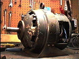
In this generators original configuration, it was driven by a 3 horsepower, single phase, 124/240VAC 60 hz, electric motor. The outputs were 12 VDC at 25 amps and 120 VAC, 400hz, at 10 amperes. The motor and generator were mounted on a steel frame and weighed in at about 150 pounds. Definitely Navy surplus, as one of the grease fittings called for Navy type grease.
I really didn't need 120VAC at 400hz, nor did I need 12VDC, as I've got generator for that. The alternative was to rewind the rotor to put out 120 VAC at 60 hz. Opening up the generator I found that it was a four pole design with pole pieces at 90 degree intervals.
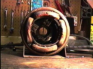
Notice that the field poles are the "shoe' type and not the "slot wound" type. These act as simple electromagnets with North, South, North, South magnetic polarities. They just supply a magnetic field for the rotor. In this design, the power is taken off of the rotor, not the stationary poles. (Other designs take the power off of the stationary poles and the field poles revolve, as in an auto alternator.) Shoe poles make great electromagnets, but are very poor as far as being to get any useful power out of. The "slot" type stators are much better at being able to put out useful power.
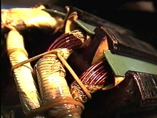
This design is somewhat unique in that the shoes are not only shoes, they have slots within the face of each pole shoe! Take a close look at the pole here:
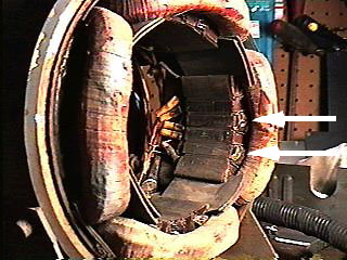
Notice where the arrows are pointing. This is where the 120 VAC at 400 hertz was taken from. Each of these windings were in series with the other slot windings in each pole shoe. I now use these windings as the power source for the field magnets and as such they run the voltage regulator. As I stated before, slot windings are a very efficient at providing power, while shoes make excellent electromagnets. So here we have a unique example of pole shoes with slot-type power output windings in the faces.
Now the rotor needed rewinding. Originally it had a DC commutator and was wound with some pretty hefty wire. I cut that wire out and cleaned the slots. Some AC generators use slip rings to get power from the rotor and that was the plan for this one. To prepare for the slip rings I insulated the commutator with a sheet of flexible fiberglass and epoxied two rings on.
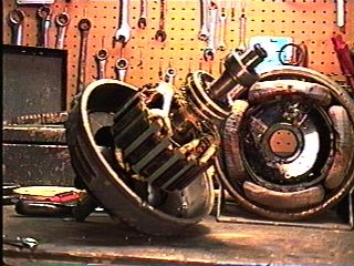
They can be seen in this picture just below the rear sealed bearing. The wiring of the rotor was a little difficult and it took me quite a while to figure out a good method to use. The #18 wire was just too heavy to neatly wind into the slots. Also, the coils had to be all in series and in the proper phase. Phasing means that one coil is wound clockwise while the next coil is wound counterclockwise, giving a N S N S polarity around the face of the rotor, just like the field poles polarity. I finally ended up making a continuous loop of wire about 6 feet long with about 40 some turns. This was accomplished by putting two large nails in an eight foot, two-by-four and winding the wire back and forth between the two nails. After covering the wire bundle with polyurethane floor varnish and some fibertape, I gently placed it into each slot, while the varnish was still a little tacky. Then the next big job was to cut each wire and solder it in series with the next wire in the bundle. This was to produce one series winding out of the whole bundle. (Yes it was series before, but it was not possible to place it in the rotor slots connected that way. ) Coating the windings with varnish helped seal the windings and the tying of the coils helped to secure them. After that tracing and soldering "fun" I connected the two ends of the loop to the two slip rings.
It actually worked the first time I fired it up. I had to do a little work on the homemade voltage regulator. It is mounted in a separate box (old 5 1/4 floppy drive box) and is basically the same as the other regulators I've used in my other generators.
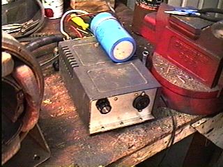
I have 4 pass transistors on the back of it heatsinked. The regulator has to power the 4 poles as electromagnets so it passes a lot of current. I think it is about 6 to 8 amps.
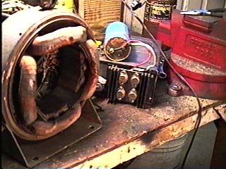
This generator now has an engine! I finally got around to making a frame and mounting the generator, regulator and engine. The engine is a 3 horsepower Briggs and Stratton that I rebuilt. NJ8V and I knurled the piston as an experiment and it worked out pretty good! Total power output is about 1000 watts maxium. The pulley ratio is such that the engine turns at 3200 RPM and the generator turns at 1800 RPM, producing 120 VAC at 60 hertz.
This has been a fun project, about 2 years in the making! I really like this manner of mounting a generator and engine. The whole system is just like a dolly (or "hand truck" as they are called) and makes it real easy to carry around to where it is needed. The tires are left overs from an old lawn mower.
Ignition static was a problem and I had to shield the spark plug wire with copper braid from some R/G 8 coax. I made a little metal "boot" to go over the spark plug and it really cuts the static. As I've said before, I am a ham radio operator and I like to operate out in the field. This generator is just looking for a radio adventure to the field!
Very 73 de NS8O Updated Oct 12, 1998