| CIRCUIT
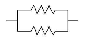
COMPONENTS The path on which voltage must flow is via a conductor - any material that will transfer electrical energy. And when choosing a good conductor, one wants to select a material that will allow flow most efficiently, without much resistance. These materials include some metals and alloys, like copper, aluminum, gold, silver, and steel. Conversely, a structure will have to be incorporated in the circuit that prevents the flow of electricity; this material is called an insulator. Wood, rubber, glass, porcelain, paper, and air make good insulators - even water is a good insulator, providing it is pure, like the deionized type. Circuit components can be found in two generic arrangements: series and parallel. In a series arrangement, two or more components will be lined up for flow without the path splitting. And in parallel arrangement, the pathway splits so that flow to components can follow more than one direction.
RESISTORS No matter what kind of circuit exists, there is some amount of resistance the flow of electrons. But sometimes, we must intentionally place resistance in a circuit to control the flow of current. Resistors are circuit components which have been especially designed to lessen the flow of electricity, but not completely stop it. Most resistors are made of carbon, which is an electrically neutral material. Resistor are designed to prevent a certain amount of current pass, and they are rated so that a designer will know which one is appropriate to use. Below is a diagram of a basic resistor:
You can see that there is a striped color-coding scheme used to rate the resistance of resistors. The first three (closest to one end) will express the value of the resistor in ohms, while the last stripe will indicate the tolerance. The tolerance will be a percentage above or below the rated value that the resistor is actually good for. Lower quality resistors have higher tolerance ratings, while precision components have small tolerance ratings. For the purpose of the test, just remember that the lower the tolerance, the better the quality of the resistor. Resistors work by transferring electrical energy into heat and then dissipating that heat at a rate that will not burn up the circuit. This is why you must be especially careful in choosing resistors for homebrew radio equipment; if you choose one that is rated above the maximum allowable current in that circuit path, it could easily burn up. Always select the larger resistor between two of the same rating for better heat dissipating. Two types of resistors are called film and wire-wound. Some resistors, called potentiometers, allow the designer or user to control the amount of resistance applied at that point along the circuit by moving a slide or contact. You are familiar with a potentiometer if you have ever turned on a variable intensity, dial-type light switch.
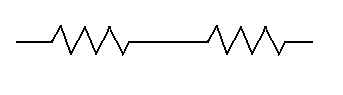
Look at the symbols below to see what resistors will be represented by in a circuit diagram:
CAPACITORS AND INDUCTORS Capacitors and inductors are both components which were designed to store energy.
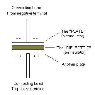
A simple capacitor is just a couple of conductors separated by an insulator. Capacitors are capable of storing energy in an electrostatic field, and are commonly used to reduce the flow of AC current while allowing DC current to pass on by. Capacitors also resist changes in voltage. A capacitor is formed from two plates separated by an insulator. The capacitor becomes charged when current from a power source flows to the plate. Electrons build up on one side of the plate resulting in a negative charge. Remember the magnetism example? Likes repel. So electrons on the other side are pushed to the positive battery terminal, resulting in a positive charge on that plate. This how the capacitor becomes charged. See the diagram below.
The capacitance of a capacitor is determined by the following four factors:
Variable capacitors are formed from two sets of rotating plates which intermesh with one another. The dielectric in this case is air, and as the plates turn away from each other, the capacitance decreases. You will be required to be able to recognize these capacitor diagrams:
Inductors are designed to hold energy within a magnetic field - it works by resisting changes in current. The simplest inductor is a basic conductor with current flowing through it, which causes a magnetic field to form around the conductor. Inductors are commonly used to reduce the flow of AC current while allowing DC current to pass on by. The inductor core is the material in the center of the magnetic field; here the field is most concentrated. The inductance of a coil is determined by four factors:
An iron core results in a high impedance. Plastic tools must be used when adjusting a core because iron (ferrite) based tools can affect the impedance. You will be required to be able to recognize these inductor diagrams:
Visit the Calculations Page for detailed information on how to add the values of resistors, capacitors and inductors. OTHER IMPORTANT CONCEPTS Open circuit: In incomplete, broken circuit in which no current can flow. Short circuit: An unintended venue of electrical flow which draws too much current - this situation can be dangerous for both the equipment and its operator! Safety interlock switch: A safety lock-out mechanism built into various high-power component cabinets and power supply connections of some radios which prevent current flow if the cabinet is off and/or the interlock is not deactivated. They should be sufficiently rated for the voltage rating and current capacity of the circuit. Shielding: The barrier in a transmitter cabinet that prevents the release of interfering radiation. DC Current: Current which only flows in one direction; the kind that batteries produce. Power supply units are used to convert AC current to DC when operating equipment designed for DC input, such as a mobile radio. AC Current: Current which flows back and forth in opposing directions; the kind produced by commercial generating stations. Grounds: Grounds are used to prevent electric shock and surges to your equipment. All radio equipment should be properly grounded to prevent damage in case of a power surge. A proper antenna ground constitutes a copper or copper-clad steel driven at least 8 feet into the ground. Connect your base antenna to it. The antenna switch can be used to switch the from a radiating antenna to the ground. The chassis of each radio component should be connected to each other and properly grounded as well.
A quick note on secondary (rechargeable) cell batteries - the two most common rechargeable batteries available for today's handheld radios are nickel-cadmiums (Ni-Cads) and Lithium-Ions. With the Ni-Cads, always make sure that you always run down your radio to zero charge before recharging. Otherwise, they will build up a memory and the lifetime of that battery will decrease.
Transistors: Transistors are the heart of today's radios, and a lot of other electronic equipment that you come across. Transistors are integrated circuits that were created to amplify a small signal using a low-voltage power supply. They have three basic components, an emitter, a collector, and a base. You must be able to recognize two types: a NPN and a PNP. Note the change in direction of the arrow to tell them apart:
Vacuum Tubes: The predecessor of the transistor. Necessity selected against vacuum tubes long ago because it took a high-voltage power supply to create a relatively small signal. Except for the test, you may never need to know anything about vacuum tubes because modern day radios just don't have them. Vacuum tubes are still used, however, in high-voltage amplifying applications. At least know these symbols:
Switches: Switches are the means of directing current from one path to the next - they open or close a circuit. Look at the symbols below, you'll have to be able to distinguish them on the exam. The pole is what changes the direction of flow, while the throw is a point of contact. Double-throws allow two inputs to be changed at one time. Switches are similar to fuses in that they are rated in amps; the switch rating must meet or exceed the amperage of the circuit that it is being applied to.
|
 Fuse: A deliberate weak link usually placed in the power and ground leads that will
"self-destruct" in case of a power surge. The fuse will burn out,
resulting in an open circuit. No problem, since they are conveniently placed and
easy to change out. Fuses are used to keep power surges from destroying the
your equipment.
Fuse: A deliberate weak link usually placed in the power and ground leads that will
"self-destruct" in case of a power surge. The fuse will burn out,
resulting in an open circuit. No problem, since they are conveniently placed and
easy to change out. Fuses are used to keep power surges from destroying the
your equipment.