| ANTENNAS
AND FEEDLINE Well, what can be said of antennas? Everything! There are a lot of important components to your amateur radio, but your antenna can make or break it, even if you have everything else tight! It's characteristics are extremely important when it comes to both receiving and transmitting.
ANTENNA TYPES Antennas can be classified into two very general categories, the omnidirectional and the directional. Omnidirectionals (non-directionals) radiate signals equally in all horizontal directions. A single element vertical ground plane antenna is the best example. It is the same type that you can buy for a mobile installation (like your existing FM car antenna) and is also the same kind that is used on HT's. It radiates energy equally in all directions. This antenna has a low-angle radiation pattern, so that it radiates more towards the horizon than towards the sky. A variation of this antenna is the 5/8 ground plane - this antenna will radiate even better horizontally, giving you better gain and the ability to reach and receive stations further away. Think of its propagation as resembling a cross-sectioned pancake.
DIRECTIONAL ANTENNAS Directional antennas give hams the ability to focus most of the emitted radiofrequency energy in one or two general horizontal directions. A Yagi antenna is a type of directional antenna that is made up of conductive elements residing on a boom. The Yagi is set up on the horizontal plane. Refer to the diagram below:
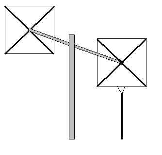
This is a simple Yagi with only three elements, the reflector, the director and the driven element. The driven element is the only powered element; it is connected directly to the feed line and is approximately 1/2 of the wavelength of the frequency that the antenna is resonant for. The director and reflector are parasitic elements. A parasitic antenna is one in which other elements obtain their energy by induction or radiation from the driven element. The director assist in focusing energy, and the reflector resist propagation of energy in the reverse direction. In this diagram, radiofrequency energy would be directed toward the left. Boom length is important for this antenna; it is the main factor in determining antenna gain. The quad, or cubical quad, is also a directional antenna, and one that is relatively easy to make on your own. It consist of elements that are fashioned into squares from conductive wire. Each wire loop is approximately one wavelength long. In the simplified diagram below, the element up front and on the right is the driven element - it is connected to the feedline. Delta loop antennas are very similar to the quad antenna, except its element are shaped like triangles rather than squares. The Yagi, quad, and delta loop antennas are all examples of parasitic beams.
Dipole antennas are cut to be approximately one-half of the frequency that they need to be resonant on. These are inexpensive antennas to put together that are used a lot when working HF. Dipoles are ideal for emergency preparedness purposes, because they are compact (a roll of wire) and easy to set up.
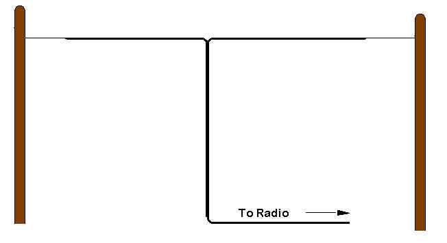
The diagram suggests that they are hung from poles, but the beauty of the dipole is that it can be secured to practically anything, as long as it reaches the required height. They are directional also - if they are hung from west to east, then their primary directions of influence will be north and south. Thick, copper-clad wire should be used instead of smaller gauges to prevent breaking or stretching. Avoid using polypropylene rope to secure your dipole as it breaks down easily under UV (sunlight) exposure. Remember this about constructing dipoles:
CALCULATING ANTENNA LENGTH AND RESONANT FREQUENCY Half-wavelength dipole antenna length (in feet) = 468 / operating frequency in MHz Quarter-wavelength vertical antenna length (in feet) = 234 / operating frequency in MHz Operating frequency of a specific half-wavelength dipole antenna (in MHz) = 468 / antenna length (in feet) Operating frequency of a specific quarter-wavelength dipole antenna (in MHz) = 234 / antenna length (in feet)
Rubber duck antennas are the ones that you see on handheld units. They are not very efficient but are used primarily if because they are sturdy and compact. These antennas can always be replaced by the telescopic whip model to increase the gain. A multi-band antenna is resonant across a few frequency bands. Using these antennas can be inexpensive, but can be a pain to set up - they are very prone to emitting unwanted harmonics when not properly tuned. Sometimes loaded coils are used to extend the resonant frequency of an antenna. These coils make the antenna act as if they are longer than they physical are.
POLARIZATION Polarization is an important concept in antenna propagation. In almost all cases, polarization is in the same plane as the physical orientation of an antenna. So if an antenna is physically lying horizontal, then its polarization will be horizontal (parallel to the earth's surface). Antennas on the same band must have the same polarization to make contact. For example, to make contact with a VHF-UHF station or repeater that has vertical antenna polarization from your HT, the unit must be kept as straight up as possible to maintain vertical polarization. Otherwise, variance can greatly diminish your signal propagation with even the slightest deviation. Yagis and quads are set up horizontally to emit; they have horizontally-aligned polarization, meaning that the receiving antennas must also have horizontal polarization. When two antennas have opposing polarizations, they are said to be cross-polarized. And when antennas are cross polarized, they can not propagate with one another. Horizontal polarization is ideal because most man-made electrical noise has vertical polarization. If these signals are cross-polarized, then the noise can not come in on these antennas. Circular polarization is utilized by satellites. Because satellites rotate so much, polarization is aligned in multiple directions in order to maintain ideal propagation with all points on the earth's surface.
FEED LINE Feed line is what is used to connect a radio with an antenna. When choosing a feed line, quality products should be selected to keep radiofrequency loss to heat at a bare minimum - so anything do you can to keep you signal from being diminished. Standard lamp cord is not a good choice for feed line - it has no protection against signal loss. Coaxial cable ("co-ax") is a type of feed line which consist of four components:
Coax cable is the feed line of choice for many amateurs because it is manufactured in many different varieties, it is weatherproof, and it can also be used around metal structures. Its also tough enough to be buried in the ground without worrying about it wearing out any time soon, just make sure that you don't jab a shovel through it when digging holes in your yard. Usually, the larger the diameter of coax, then the less signal loss that can be expected. Look at these types of coax to see which are appropriate for different applications:
Twin-lead feed line is also available; it is pre-manufactured wire encased in plastic and separated at a uniform distance throughout the length of the line. You may have used this at one time to connect your TV to a VHF antenna. Parallel conductor feed line consist of two conductors held apart by insulating rods. It is also called "ladder-line" because it resembles a ladder when it is strung up. Ladder-line will operate with a high SWR and has little loss compared to coax, but the biggest drawback is that you have to construct it yourself (it's homebrew all the way) - it's hard to install properly. Its not an easy task, but may be well worth it. Principles of Feed Line: Important
Concepts to Remember More definitions: Balanced line is a feedline made of 2 parallel conductors with a uniform space between them. Unbalanced line is a feed line with one conductor connected to the ground. Baluns are devices which have been designed to interface with two different impedances in case there is a mismatch between the feedline and the antenna. The word "balun" is a combination of the words "balanced" and "unbalanced". A balun can be constructed from a toroid, a length of transmission line, or a pair of air-wound coils.
CONNECTORS There are many types of connectors used for connecting radio equipment, feedline, and antennas. Connectors can be another weak link in signal strength, so always use high quality connectors and make sure that they are clean and well maintained to prevent signal loss.
Antenna switches are devices that have connections for multiple antennas; you can select between different antennas or to a dummy load or a ground.
ADDITIONAL INFORMATION
|