Building a Network
The computer required for your network doesn't have to be anything special, though you may want to consider a dedicated router, as stated previously. It doesn't have to be anything valuable. I use an old 25 MHz 486 with 12 MB RAM and a 170 MB disk drive. See the dmesg output here. It runs just the minimal amount of daemons, and doesn't have a monitor or keyboard attached. Its sole purpose is to route the wireless network.
A side note, you may also want to assign your IP address' in the 10.x.y.z range. You can then break them up where x = city, y = house, and z = machine, or any other possible way you can think of. This will help organize your network. Also, assign host names in a reasonable fashion as not to confuse new network administrators.
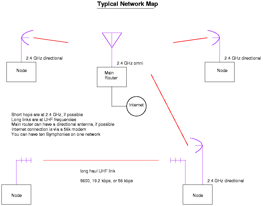
You may also have to resort to other transmission methods if your network is to span long distances, go through high interference areas, or if you have a large number of nodes in your network. Unused UHF television frequencies make a great place to put long haul backbones on. You can then use conventional television antennas for each node. UHF links also propagate through interference alot better than microwaves, and they are almost always noise or interference free. A typical network map is shown here.
A list of success stories will try to be maintained. If your low cost wireless network works, be sure to let us know.
Homebrew Test Equipment & Software
Here is the new section on homebrew test equipment and software.
Link Quality Graphs Using GNUplot
For a graphical overview of your network's latencies you may want to look into GNUplot. GNUplot is a very powerful interactive function plotting program. You can get more information about it at this site. For a quick example, type the following commands.
- Step 1
- script
-
- Step 2
- ping -c 1000 192.168.3.2 # insert your host here
-
- Step 3
- Let this command run while you adjust your antenna or cable positions.
-
- Step 4
- exit # exit script
-
- Step 5
- cp typescript typescript.orig # backup
-
- Step 6
- grep ^64 typescript | awk '{print $7}' | awk -F= '{print $2}' > out
Gets all the lines that are ping millisecond output.
-
- Step 7
- gnuplot # you did remember to install it?
-
Type these next commands at the gnuplot> prompt.
- Step 8
- set ylabel "milliseconds"
-
- Step 9
- set xlabel "ping count"
-
- Step 10
- set title "GNUplot is hard to use"
-
- Step 11
- plot "out" with impulses
You'll then get a graph, sorta like this: ![[ping1]](pics/small/ping1.jpg)
This is a graph of one thousand ping's on an idle network with a strong received signal level.
Initial outside test networking graph: ![[ping]](pics/small/ping.jpg)
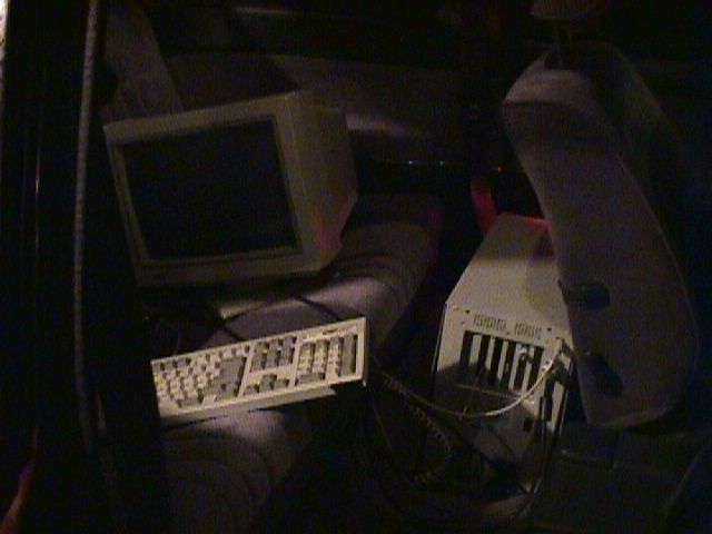
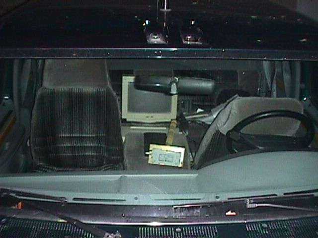
Here is a picture of the initial mobile test setup. The Mighty Packard Bell powered off a 300 Watt DC to AC power inverter, a California Amplifier 22 element Yagi antenna, and about 3 meters of LMR-400 with N connectors. Another picture of the second mobile test setup, same components, just better results.
The peaks at around ping count 75 and 375 were caused when the test directional antenna was rotated. The plateaus at 10,000 milliseconds are where the link had actually dropped out, and I edited the script command output file to represent that.
To get PostScript output files from GNUplot, use the commands: 'set term postscript portrait color' and 'set output "filename.ps"' before the plot command.
To set a limit on the x or y range, type 'set xrange [0:1000]' or 'set yrange [0:2000]', where the [0:???] part is the numeric range your want your graph to stay within. You can also enable a grid for you graph with the command 'set grid'.
Here is what that would look like: ![[mobile_test-1]](pics/small/mobile_test-1.jpg)
This procedure of using 'pings' for alignment will not always work with direct sequence spread spectrum systems (DSSS) as they are more of a hit-and-miss type of setup. You'll either have a good link, or not have anything at all.
Link Quality Testing Using Netperf
Netperf is a benchmark that can be used to measure various aspects of networking performance. Currently, its focus is on bulk data transfer and request/response performance using either TCP or UDP, and the Berkeley Sockets interface. In addition, tests for DLPI, the Fore ATM API, Unix Domain Sockets, and HP HiPPI LLA may be conditionally compiled-in.
Here are some Netperf results on a Symphony based network with a strong received signal. The computer slave is a 100 MHz Pentium, master is only a 486, both are using Linux kernels version 2.2.13.
Here is a little tidbit on the relatively high latencies. Under frequency hopping systems, the receiver needs to syncronize both time and frequency on both ends of a link. This is a very difficult to implement efficiently in the low cost cards used today. They'll spend most of their time searching for the proper signal to lock on to. This results in increased latency times. In DSSS only the timing of the receivers needs to be synchronized. This can usually be done by just receiving a few bits of data.
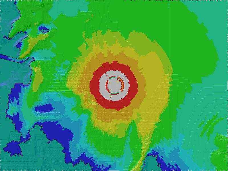
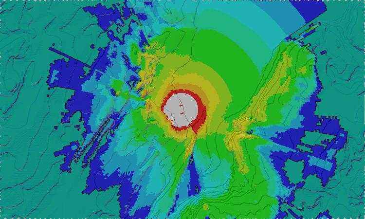
Radio Coverage Maps With Radio Mobile Deluxe
It is possible to use freeware software by VE2DBE to approximate and map the RF coverage area of your transmitter. It uses freely available terrains data from the government to provide resolutions to three arc seconds (100 meters). For more information, visit the Radio Mobile Deluxe website.
Security
Physical layer security in wireless networks is an extremely important issue that most people overlook. This is because manufactures claim their networking products are immune to interception or destruction of data. See the Resurrecting Duckling's recent paper on some common wireless network security issues.
Some of the following examples might be frequency dependant, but the concepts will apply to all wireless applications.
Security Myth One
2.4 GHz wireless networks operate at frequencies a normal person can't receive.
Remember earlier when you went out antenna scavaging and I said grab the downconverter if you can? Well, that's because it's a very useful piece of engineering. The downconverter's purpose is to receive and amplify a 2.5 GHz television signal, then mix it with a 2.278 GHz local oscillator signal. The mixing between the 2.5 GHz and 2.278 GHz signals makes a new signal at 222 MHz (2.5 - 2.278 GHz). This new signal at 222 MHz contains the same data in the 2.5 GHz signal, just at a frequency easier to work with. This entire process is called heterodyning. It's this new lower frequency that would get sent down to your television set.
Now, what if we were to bypass the downconverter's stripline filters and expand its receive coverage down to 2.4 - 2.4835 GHz? Why, the downconverter will convert this into a 122 - 205.5 MHz signal which we can easily receive using a communications receiver with a wider IF filter and receive front end modifications. Two and four level frequency shift keyed FHSS signals should be easy to decode using a common op-amp data slicer on the receiver's discriminator tap. You would just have to find a way to keep up with the frequency hopping. Side note, this won't work on DSSS systems, or may not even work at all... Here are the preliminary test results.
This reenforces the need for strong application level security. Don't trust any of the hardware manufactures and their, sometimes, outrageous claims. GNU Privacy Guard and OpenSSH will provide you with privacy and encryption on your wireless network, even if the link is hijacked or compromised.
You may also wish to construct a TaborRampart router/NAT/SSH/PPP/VPN device as a single disk solution to most of your security problems.
Visit the SecurityFocus website for more solutions on security and virtual private networks.
Security Myth Two
2.4 GHz wireless networks operate at frequencies that can't be jammed.
The 2.4 GHz band is open for unlicensed FCC compliant Part 15 ISM (Industrial, Scientific, Medical) devices in order to allow the public to reclaim their rights to the airwaves. This band is currently being used throughout the United States for a variety of applications, and also, for our friend the microwave oven.
Microwave ovens are essentially large continuous wave radio transmitters (50% duty cycle, 16 ms periods, 10 MHz bandwith) that operate at 2.45 GHz. At this freqency, water molecules have a high absorbtion factor (They do not resonate). Which explains why microwave ovens can cook food and rain and trees can ruin a wireless network link.
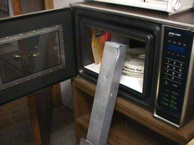
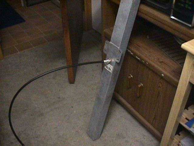
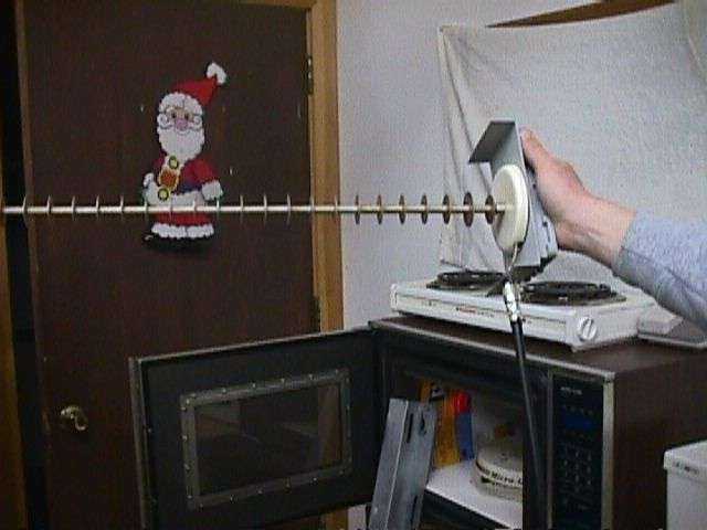
A properly mantained microwave oven will radiate very little power. Typical field strengths are approximately 100 µV at 300 meters. They also shouldn't effect the operation of other devices operating in that frequency range, in the same area. It's just when you take off the microwave's door shielding, and attach a very long extension cord that the fun begins.
Theoretically, you could buy or build a 2.4 GHz waveguide-to-coax transistion and concentrate microwave oven radiation at your target using a directional antenna. You should be able to takedown a wireless network, and a few birds, all in one shot! I'm serious. You could even control the airwaves by charging a toll for ISPs to shoot a wireless link over your house. If they don't pay, accidently forget to turn your microwave oven off. Oops. Picture one, two and three.
Frequency hopping spread spectrum systems usually make their initial synchronization possible by parking on a fixed handshake frequency before starting their hopping sequence. If you were to jam this parking frequency, the system would not be able to synchronize itself, and communication would be impossible.
Another overlooked area is the exterior antenna location. In order to achieve a line-of-sight condition, the transmit and receive antennas are mounted on towers or poles that almost always lack physical security. Any person could score the coaxial cable's exterior covering causing water damage over a period of time, or in some cases just cut through the coax altogether. People have also been known to shoot BB guns or .22 rifles at coax cables on towers located near forests, rural areas, or the ghetto.
Other Security Ideas
Another possiblity for destruction is the removal of lightning protection on the tower or coaxal cable. This won't show up as any degradation of the signal until it's too late. A nearby lightning strike will induce a large voltage spike that will head undeterred into sensitive electronics, hopefully causing extensive fire damage.
A winter time favorite is to throw snow balls at microwave link antennas. Even if you can't damage the antenna, just causing a few degrees of link mismatch will degrade, or ruin a wireless link. You may even force them into using a less secure link for their backup. We won't even get into the strike force birds which silently attack antennas...
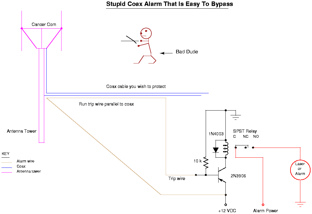
In order to prevent all these from happening, locate your antenna or tower in a well lit, well maintained area. You may even want to consider seismic sensors or other intrusion detectors that will notify you of an incoming invasion. You could also run some old telephone wire parallel to your coax cable, then run current through the wire. Sort of like a poor man's normally closed burglar detector. Vandals will often cut the entire cable bundle not knowing that the telephone cable is really an alarm rigged to a siren or spotlight mounted somewhere nearby. A diagram of this type of alarm.
It may seem like common sense, but there are enormous security holes at just about every commercial antenna or tower installation. Don't allow your installation to fall to such simple actions.
![[ping1]](pics/ping1.jpg)
![[ping]](pics/ping.jpg)
![[mobile_test-1]](pics/mobile_test-1.jpg)