AeroComm CL4490 Experiments
Overview
Here are some experiments we are doing with AeroComm CL4490-1000 ConnexLink one watt, 900 MHz Frequency Hopping Spread Spectrum (FHSS) RS-232 transceivers. These individual transceivers are available from Mouser Electronics (Part Number: 814-CL4490-232-C) for approximately $110 each. Experimenters may wish to pick up the starter pack, which includes two transceivers, software, cables, and rubber duck antennas (Part Number: 814-CL4490-232-SP) for approximately $225.
The actual RF module itself (AC4490) can be bought for around $62 (Part Number: 814-AC4490-200M). The complete AeroComm CL4490 transceiver includes the AC4490 module housed in a nice aluminum case with an internal switching power supply and the necessary RS-232 to TTL conversion circuit. The antenna connection is via a Reverse Polarity SMA (RPSMA). The CL4490 also includes four handy LEDs which indicate DC power (PWR), link establishment (LINK), when it is receiving (RX), and when it is transmitting (TX).
Digi-Key sells a handy "SMA Reverse Polarity Plug to SMA Jack" (Part Number: ACX1248-ND) adapter which changes the CL4490's reverse polarity SMA connector into a normal SMA connector.
Point-to-Point CL4490 Configuration
Use the Connex4490 Configuration Utility to configure one of the transceivers as a "server" and the other as a "client." For this particular operation, we'll be using them in a point-to-point network. Each network configuration needs at least one server transceiver. The LINK LED will light up on a CL4490 configured as a server, and it will alway be transmitting data.
You may have to fiddle with your computer's serial port speed settings. Stock CL4490s come preset with an interface speed rate of 57,600 bps. Only after everything appears to be working should you increase the data rate up to 115,200 bps. Hardware flow control will also be needed to avoid overunning the transceiver's transmit buffer.
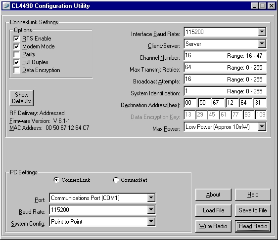 Example Server Config Screen Shot
In point-to-point mode, the server will need the MAC address of the client CL4490. In this particular example above, the "Destination Address" is set to the client's MAC address of '00 50 67 12 64 31'. Also note that the output power has been dropped to "Low Power" or approximately 10 mW. This is because this unit will be using an external RF power amplifier. In Part 97 amateur radio operation, DES encryption should not be enabled.
Under ConnexLink Settings, "RTS Enable" is selected. This is to enable hardware flow control between the CL4490 and the host computer. Also note the "Full Duplex" option is selected. This is because the two CL4490 transceivers will be using a serial PPP connection under Linux. PPP requires full duplex operation, or at least the simulated full duplex operation the CL4490s offer. This will cut the overall data rate in half.
 Example Client Config Screen Shot
Be sure the "System Identification" and "Channel Number" match the server's configuration. Also double check that "Full Duplex" is enabled. All transceivers on the same network will need the "Full Duplex" option selected.
Point-to-Point Linux Configuration
The following steps will be done using Red Hat 9.0 with a 2.6.18 kernel.
Once the CL4490s are configured under Windows, using them under Linux is quite easy. For this particular network link, we'll be using the standard Point-to-Point Protocol (PPP) daemon included in most Linux distributions.
First, you'll need to make sure you have PPP networking enabled in your kernel, or at least have it compiled as a module. Check the file '/usr/src/linux/.config' for something like this:
CONFIG_PPP=y
# CONFIG_PPP_MULTILINK is not set
# CONFIG_PPP_FILTER is not set
CONFIG_PPP_ASYNC=y
# CONFIG_PPP_SYNC_TTY is not set
CONFIG_PPP_DEFLATE=y
CONFIG_PPP_BSDCOMP=y
# CONFIG_PPP_MPPE is not set
# CONFIG_PPPOE is not set
The 'CONFIG_PPP=y' and 'CONFIG_PPP_ASYNC=y' options are a must. The PPP compression options are optional, but recommended.
Using standard DB-9 serial cables, connect the server CL4490 to one of the computers on your network and the client CL4490 to the remote computer.
Under real-world, true urban city environments (non line-of-sight), don't expect to get any more than two miles distance between them. Pagers and other in-band Part 15 devices will destroy your wireless link when operating in the 900 MHz band. Be sure to use antennas with the highest gain possible to help reduce receiving any external interference. Also, try using horizontal polarization for the antenna to further reduce interference from high-powered pager systems.
Next, you'll need to configure both the client's and server's PPP options. Under the '/etc/ppp' directory, create an 'options.ttyS0' file ("ttyS0" is COM1, otherwise use "ttyS1" for COM2), and edit it so it looks something like this:
Antennas used for testing:
# CLIENT Configuration - /etc/ppp/options.ttyS0
#
# Create a UUCP-style lock file for the serial device.
lock
# Serial port speed.
115200
# Set the async character map to 0.
asyncmap 0
# Use hardware flow control (i.e. RTS/CTS).
crtscts
# Don't use the modem control lines.
local
# Enables connection debugging facilities.
debug
# Do not exit after a connection is  terminated.
persist
# Do not require the peer to authenticate itself.
noauth
# Sets the Maximum Transmit Unit value. (or should it be 256?)
mtu 296
# <local_IP_address>:<remote_IP_address>
192.168.3.2:192.168.3.1
#
# Optional stuff for when things start to get buggy.
#
# Compression appears to be buggy on these links.
nodeflate
nomagic
noccp
#novj
#nopcomp
#noaccomp


# SERVER Configuration - /etc/ppp/options.ttyS0
#
# Create a UUCP-style lock file for the serial device.
lock
# Serial port speed.
115200
# Set the async character map to 0.
asyncmap 0
# Use hardware flow control (i.e. RTS/CTS).
crtscts
# Don't use the modem control lines.
local
# Enables connection debugging facilities.
debug
# Don't transmit LCP packets to initiate a connection.
silent
# Do not exit after a connection is  terminated.
persist
# Do not require the peer to authenticate itself.
noauth
# Sets the Maximum Transmit Unit value. (or should it be 256?)
mtu 296
# <local_IP_address>:<remote_IP_address>
192.168.3.1:192.168.3.2
#
# Optional stuff for when things start to get buggy.
#
# Compression appears to be buggy on these links.
nodeflate
nomagic
noccp
#novj
#nopcomp
#noaccomp
On the server side, you need to change "192.168.3.2:192.168.3.1" to "192.168.3.1:192.168.3.2". The "silent" option keeps the PPP daemon from timing out.
The client CL4490 will be using the IP address of 192.168.3.2 while the server's IP address will be 192.168.3.1. You may wish to further edit any PPP options to fit your particular need, especially in the way of network routing and the various compression options.
Now you are ready to start the PPP connection on each end. You can use shell scripts, or even edit '/etc/inittab' to bring up the PPP link on startup. For the inital link testing, it is best to do everything manually in a separate terminal where you can watch any debug or error messages.
Open a terminal and issue the command 'pppd /dev/ttyS? nodetach' on each host computer on the link. The 'ttyS?' option is the serial port the CL4490 is connected to and the 'nodetach' option keeps the PPP daemon from running in the background. This will then display the PPP daemon's debugging or error messages locally. You may need to be 'root' in order to run the PPP daemon or to load the necessary modules. When everything is configured properly you can run the PPP daemon in the background.
Example of starting the PPP connection on the server end:
# pppd /dev/ttyS0 nodetach
using channel 34
Using interface ppp0
Connect: ppp0 <--> /dev/ttyS0
sent [LCP ConfReq id=0x1 <asyncmap 0x0> <pcomp> <accomp>]
rcvd [LCP ConfAck id=0x1 <asyncmap 0x0> <pcomp> <accomp>]
rcvd [LCP ConfReq id=0x1 <asyncmap 0x0> <pcomp> <accomp>]
sent [LCP ConfAck id=0x1 <asyncmap 0x0> <pcomp> <accomp>]
sent [IPCP ConfReq id=0x1 <addr 192.168.3.1> <compress VJ 0f 01>]
rcvd [IPCP ConfReq id=0x1 <addr 192.168.3.2> <compress VJ 0f 01>]
sent [IPCP ConfAck id=0x1 <addr 192.168.3.2> <compress VJ 0f 01>]
rcvd [IPCP ConfAck id=0x1 <addr 192.168.3.1> <compress VJ 0f 01>]
local  IP address 192.168.3.1
remote IP address 192.168.3.2
And then on the client end:
# pppd /dev/ttyS0 nodetach
using channel 2
Using interface ppp0
Connect: ppp0 <--> /dev/ttyS0
sent [LCP ConfReq id=0x1 <asyncmap 0x0> <pcomp> <accomp>]
sent [LCP ConfReq id=0x1 <asyncmap 0x0> <pcomp> <accomp>]
rcvd [LCP ConfReq id=0x1 <asyncmap 0x0> <pcomp> <accomp>]
sent [LCP ConfAck id=0x1 <asyncmap 0x0> <pcomp> <accomp>]
sent [LCP ConfReq id=0x1 <asyncmap 0x0> <pcomp> <accomp>]
rcvd [LCP ConfAck id=0x1 <asyncmap 0x0> <pcomp> <accomp>]
sent [IPCP ConfReq id=0x1 <addr 192.168.3.2> <compress VJ 0f 01>]
rcvd [IPCP ConfReq id=0x1 <addr 192.168.3.1> <compress VJ 0f 01>]
sent [IPCP ConfAck id=0x1 <addr 192.168.3.1> <compress VJ 0f 01>]
rcvd [IPCP ConfAck id=0x1 <addr 192.168.3.2> <compress VJ 0f 01>]
local  IP address 192.168.3.2
remote IP address 192.168.3.1
# ifconfig ppp0
ppp0      Link encap:Point-to-Point Protocol
          inet addr:192.168.3.1  P-t-P:192.168.3.2  Mask:255.255.255.255
          UP POINTOPOINT RUNNING NOARP  MTU:296  Metric:1
          RX packets:2083 errors:0 dropped:0 overruns:0 frame:0
          TX packets:2095 errors:0 dropped:0 overruns:0 carrier:0
          collisions:0 txqueuelen:3
          RX bytes:3076922 (2.9 Mb)  TX bytes:83972 (82.0 Kb)
Example interface configuration. Remove a set multicast flag with 'ifconfig ppp0 -multicast'.
The new interface will be 'ppp0', and you can then adjust your local network routing accordingly.
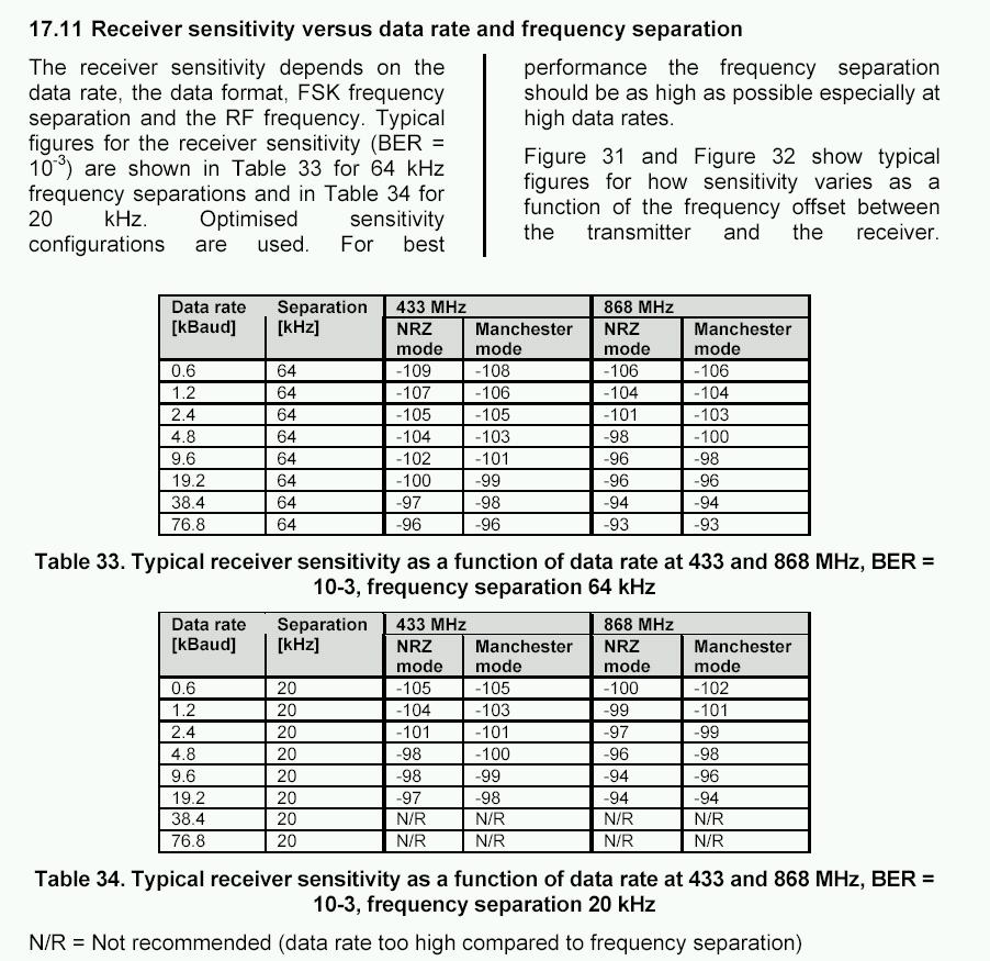
Performance wise, don't expect too much. True data rates are only around 20 kbps or so. The data rate will slow as the received power level drops off (the CC4490 manual says -99 dBm for 76 kbps). The receiver sensitivity versus data rate chart plots the Chipcon CC1010's required signal strength for the data rate you want.
Also, for some reason, the PPP compression options don't appear to work. When they do work, they are disabled by the PPP daemon after encountering any heavy traffic. The link can stall when passing high-throughput TCP/IP traffic, like when using FTP. These modules were designed for short, burst-type traffic and are not ideal for this application, but they do work.
The CL4490's "over-the-air" RF data rate is fixed at 76.8 kbps. When running in addressed acknowlegement mode, this drops in half to around 38 kbps. Then, when you change to full duplex mode, this further cuts the data rate in half to around 19 kbps. 19 to 24 kbps appears to be the maximum data rate you'll be able to get out of these when transmitting normal TCP/IP traffic.
Pictures
Click on image for larger view.
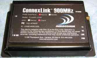
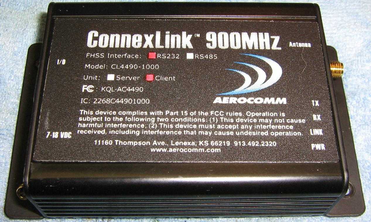
Stock AeroComm ConnexLink, Model CL4490-1000. The FCC ID is KQL-AC4490. Search for equipment authorization at the FCC ID Search.
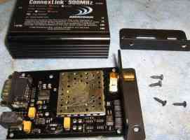
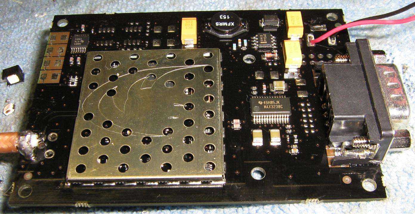
Internal CL4490 view. The antenna connection, on the right side, is a reverse polarity SMA jack. Serial connection is a standard male DB-9. DC power can be between +7 and +18 VDC and the current draw is around 700 mA on transmit and 30 mA on receive.

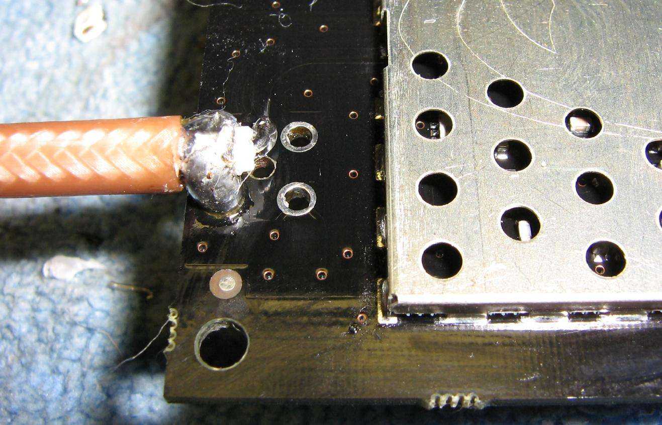
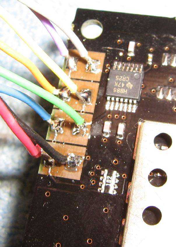
Remove the RPSMA jack, and solder on a normal coaxial pigtail. Be very careful not to lift any traces (like shown above) or to damage the circuit board. Cut off the legs on the RPSMA jack using a Dremel tool if you are having difficulty unsoldering the jack.
To make panel mount LEDs, remove the stock surface mount LEDs inside the CL4490. Break off the tops using a side cutters, and then unsolder them. Be sure to note the anode/cathode on the stock LEDs!
You can also add two wires for the DC power at this time. The RED wire shown above is +15 VDC. The BLACK wire is ground.

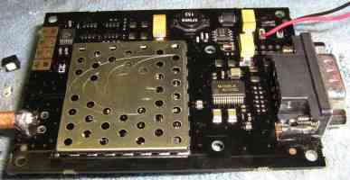
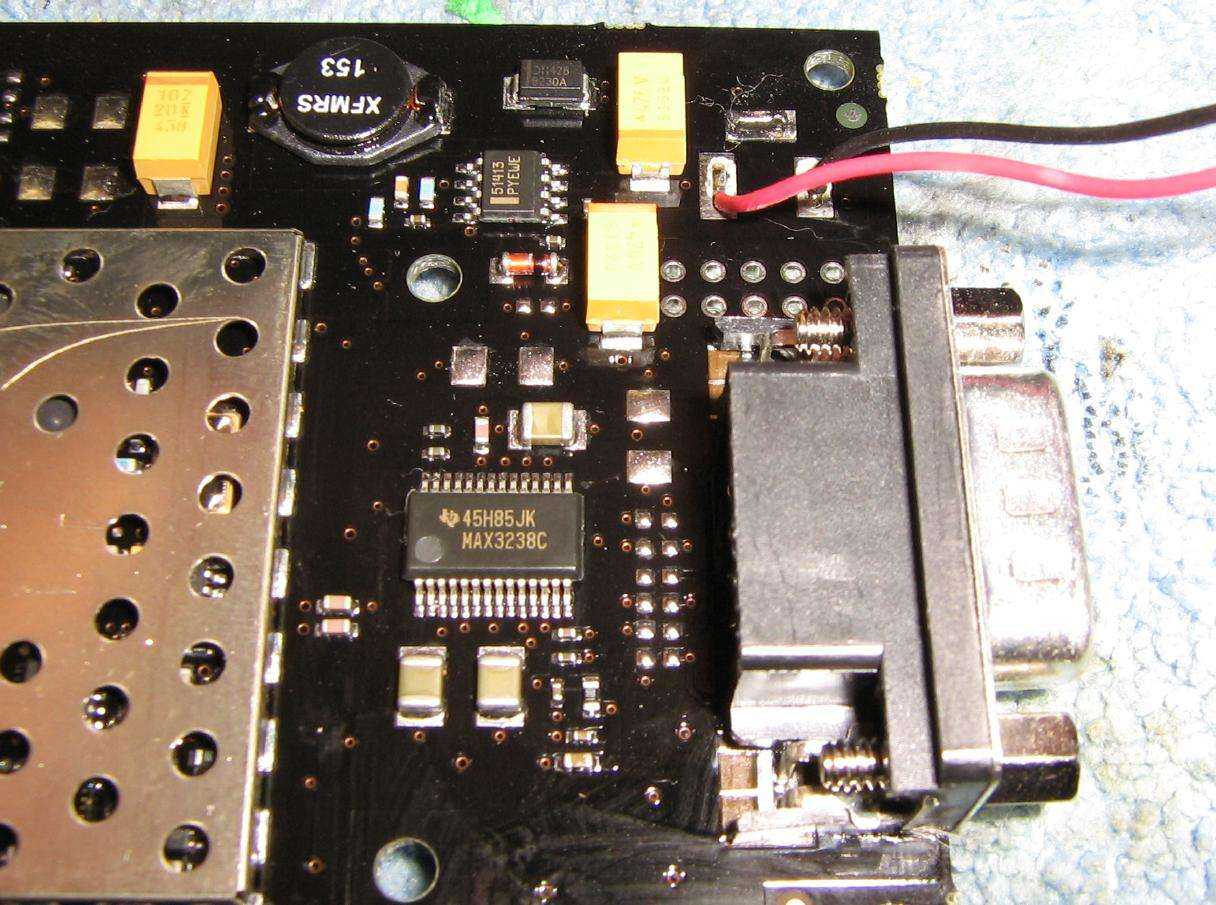
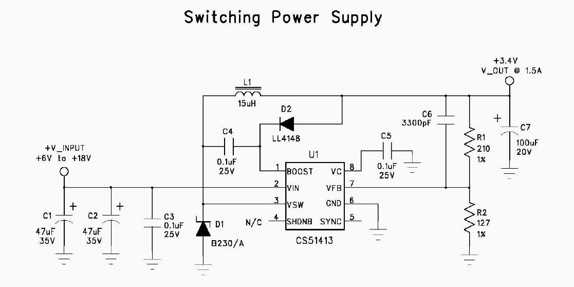
Close up picture of the input DB-9 serial connection, the RS-232 to TTL converter (MAX3238), the DC power input, and the board's switching power supply. There appears to be a number of solder pads, which may be useful as tap points.

Solder the extension wires for the new panel mount LEDs.
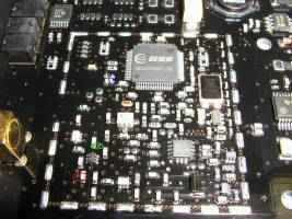
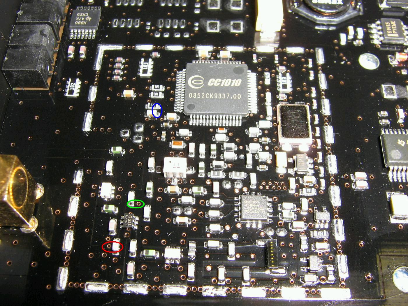
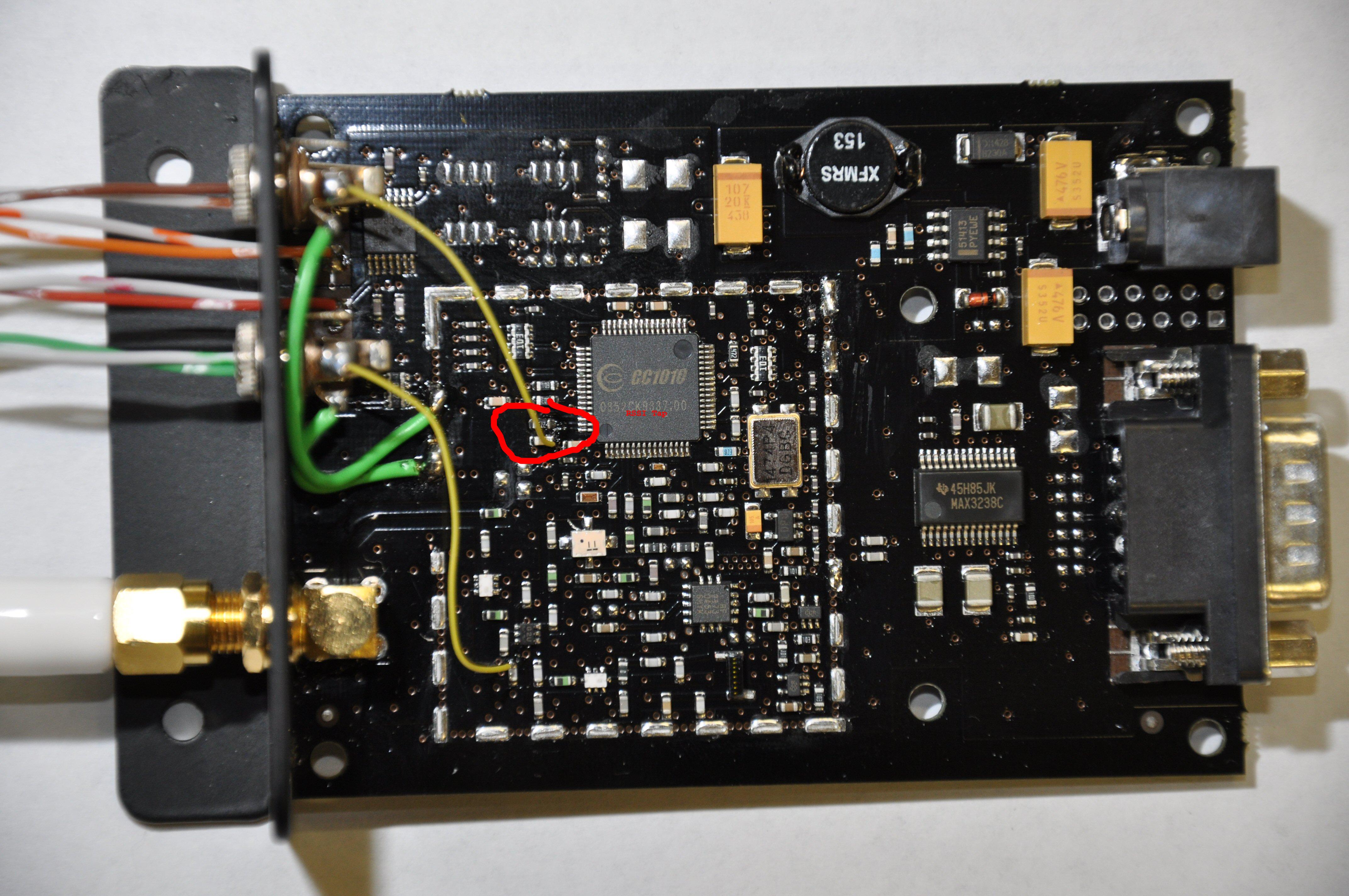
View underneath the shielding. The "System-on-Chip" is a Chipcon CC1010 RF transceiver.
The BLUE circled pad is a tap point for an external RSSI indication. (There might be a better place to tap this.)
The output RX/TX switch is a NEC UPG2009TB. The RED circled copper pad is a tap for a line that goes +3 VDC on TRANSMIT (0 on RX). The GREEN circled copper pad is a tap for a line that goes +3 VDC on RECEIVE (0 on TX).
The CL4490's final RF power amplifer is based around a RF Micro Devices RF2173 variable RF power amplifier.
The largish, white rectangular things are bandpass filters.
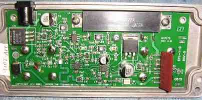
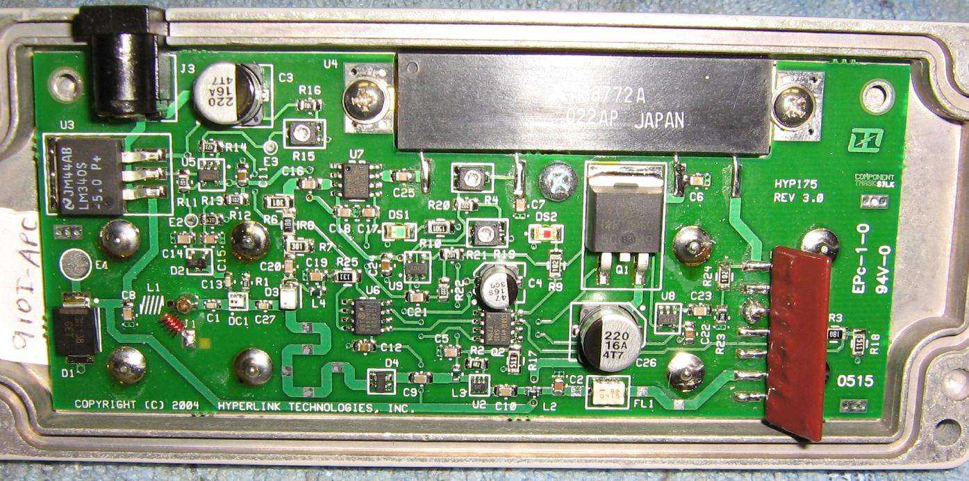
Internal picture of a HyperLink Technologies HA910I-APC 10 Watt (+40 dBm) amplifier.
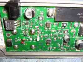
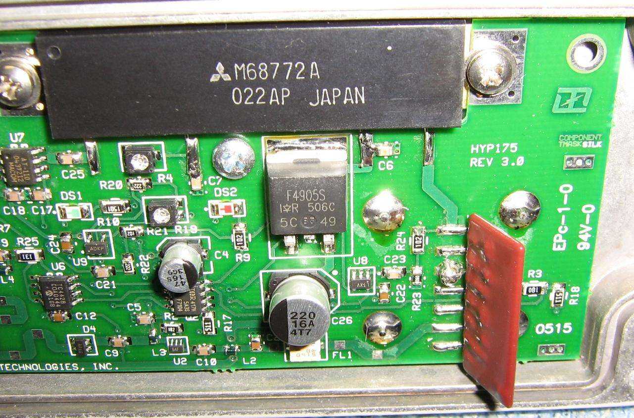
Closeup of the directional coupler / RF sense circuit, variable attenuator input and M68772 RF power amplifier, and the receive amplifier output.
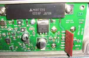
Closeup of the RF power amplifier output, the MD003 PIN diode switch, and the receive amplifer input. Note the lack of a lowpass filter or any type of 1/4-wave grounding for lightning protection. Be sure to add these externally.
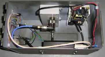
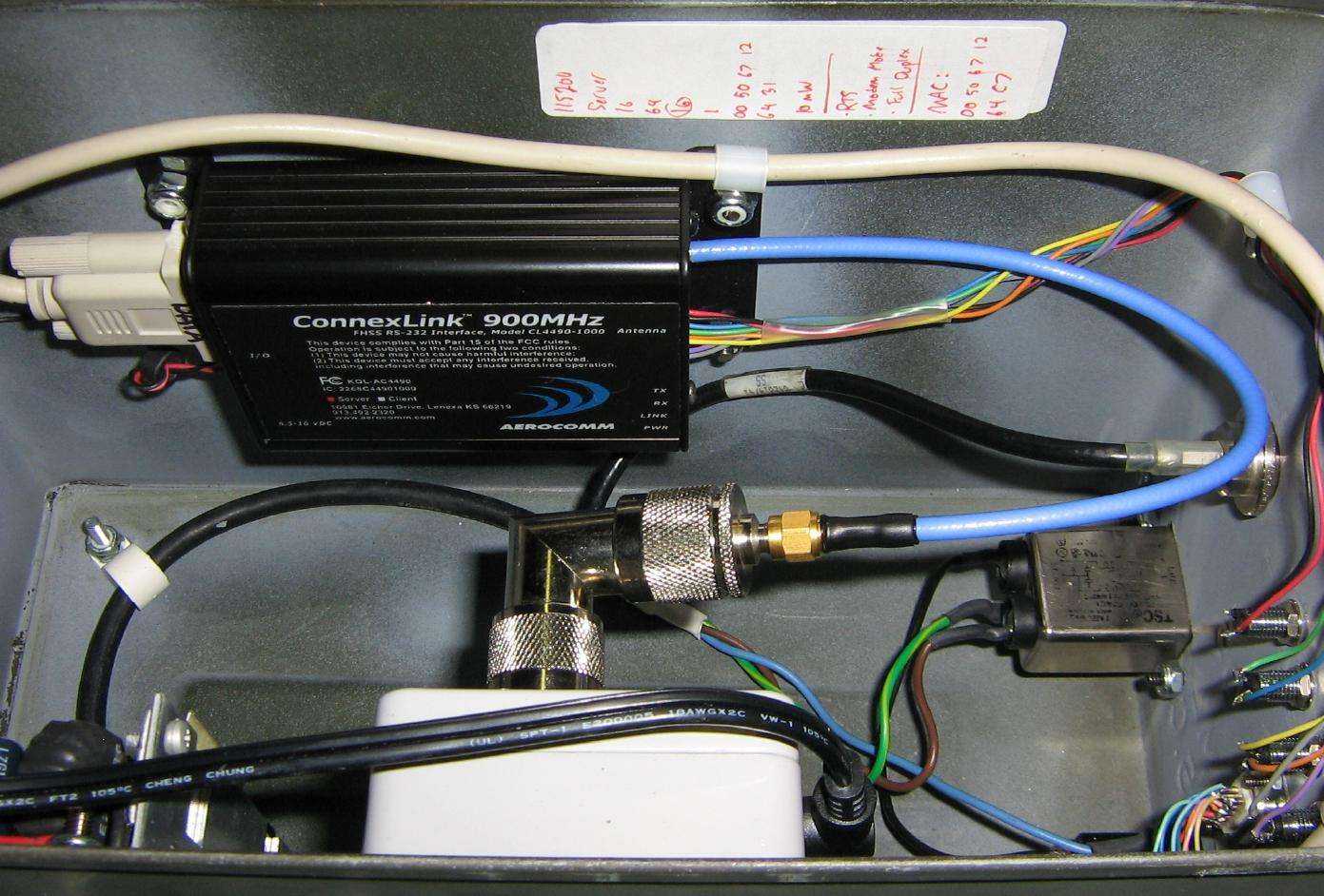
New case overview. The HyperLink amplifier and its associated +15 VDC power supply are mounted on one side, the modified CL4490 is on the other. The LEDs are all now panel mounted, along with a new male DB-9 serial connector. 120 VAC input is via a fused and filtered connection. The final RF output from the amplifier is sent to a panel mount N connector.
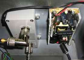
Closeup picture of the 900 MHz bi-directional amplifier and power supply. A large ferrite bead and MOV were added to the power supply's AC input line. There is also a large ferrite bead on the incoming serial line.
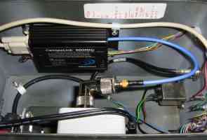
Alternate view.
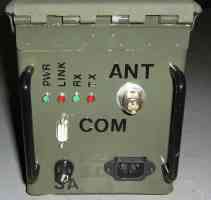
Front-panel view.

AeroComm CL4490 RSSI signal meter experiments.
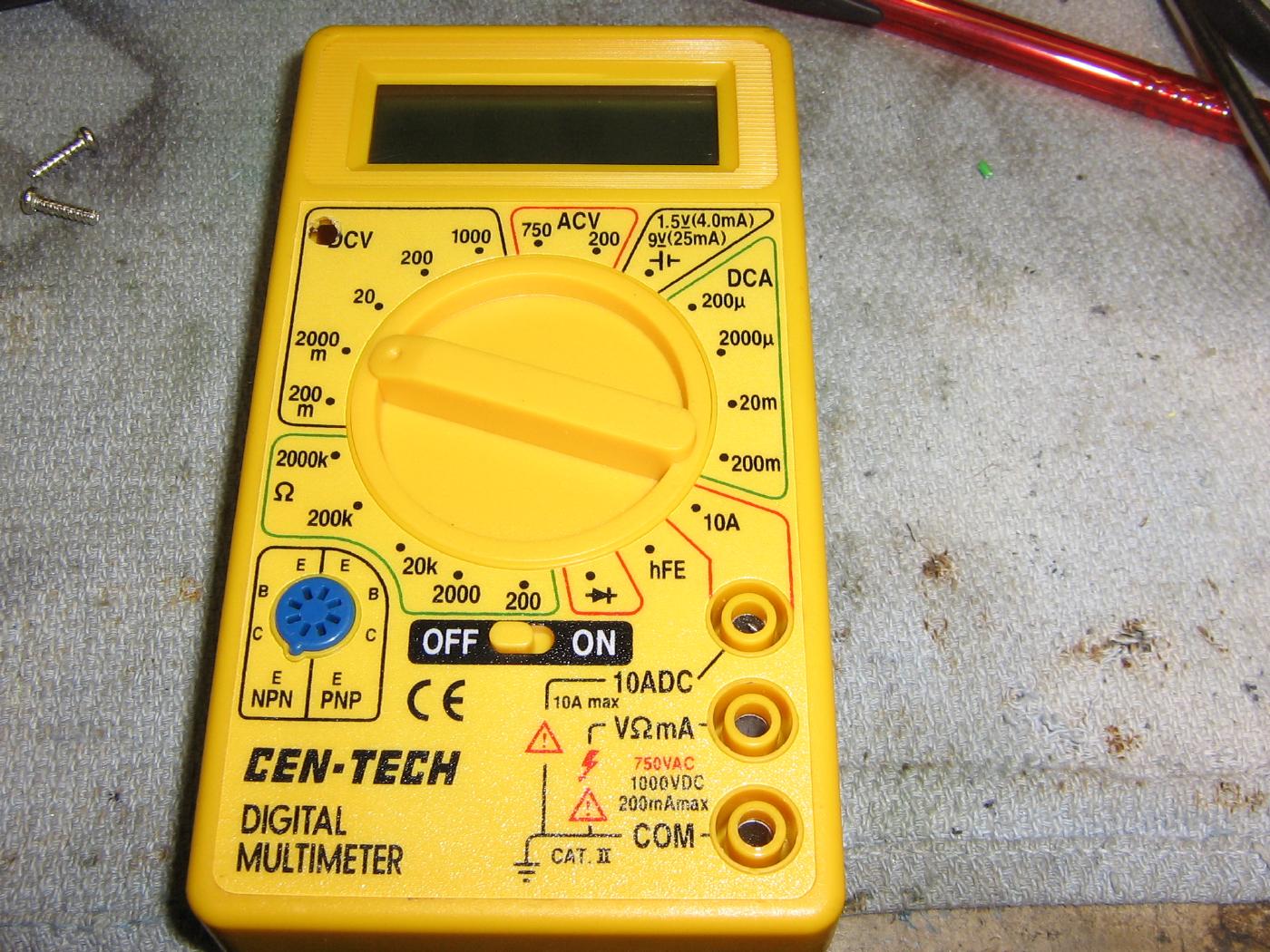
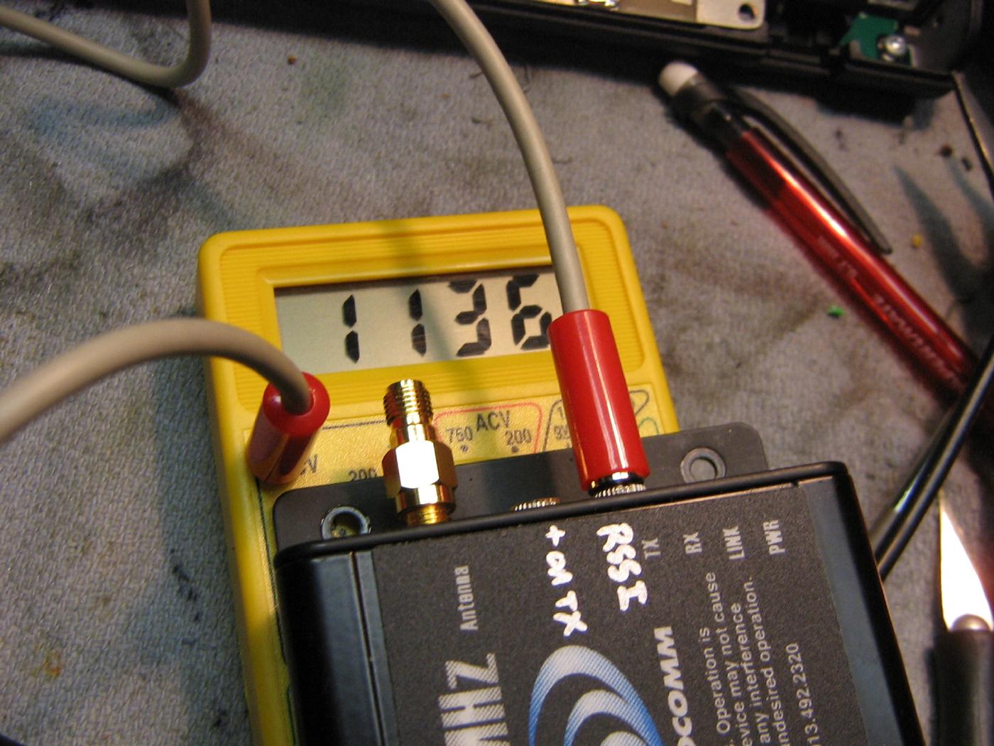
The RSSI pin on the internal CC1010 chip will be tapped and sent to be read on a cheap Harbor Freight multimeter.

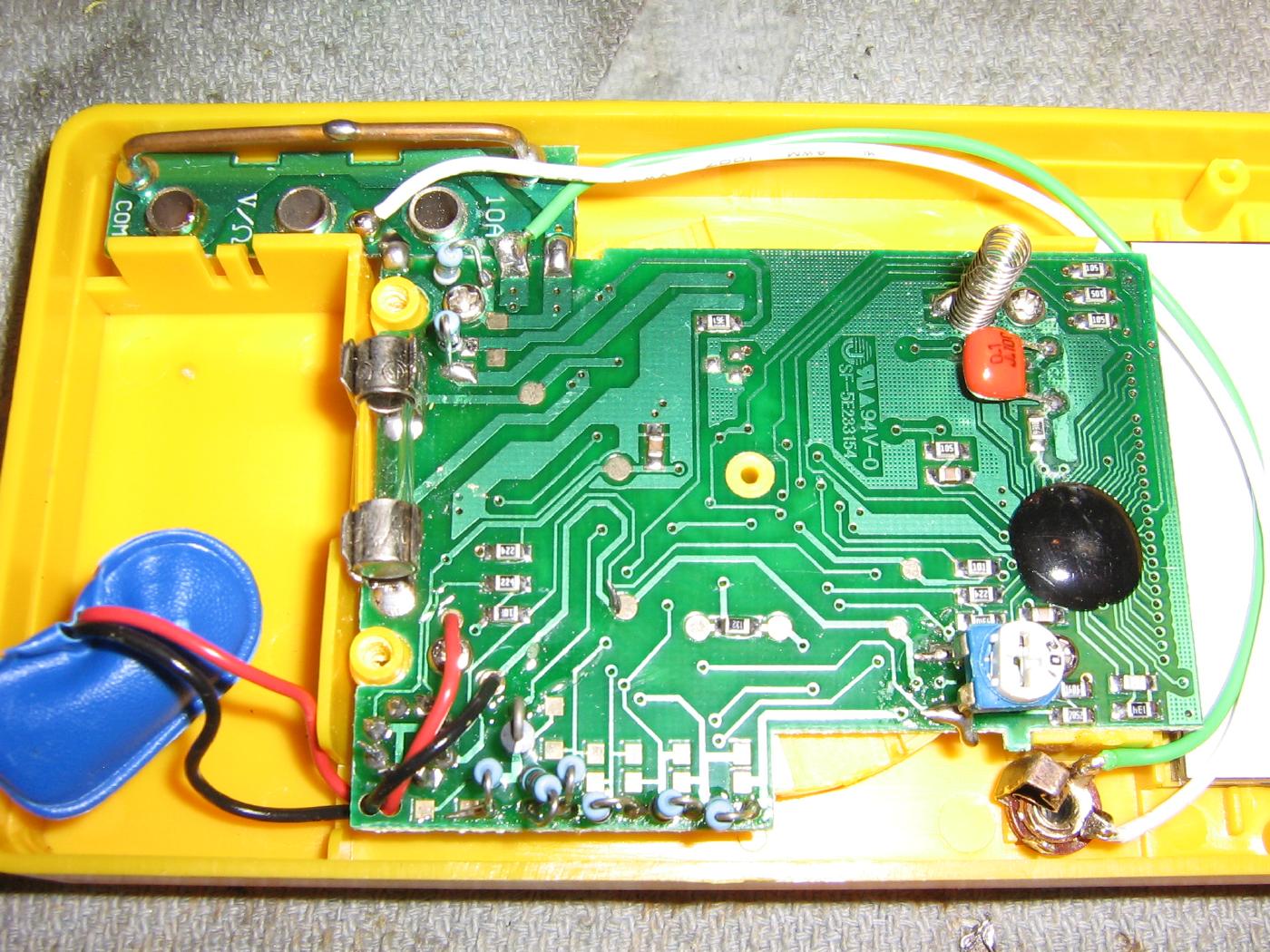
Inside the multimeter, a 3/32" jack was added to the front cover and the wires soldered to the meter's respective banana jacks.
Tap the CC1010's RSSI output as described above. Mount a 3/32" jack on the AeroComm's front-panel for convenience.

Set the multimeter to the "2,000 millivolt" range and connect it to the AeroComm unit with a 3/32" plug jumper.
This is the reading without any signal present (1,136 millivolts).
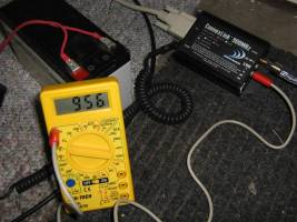
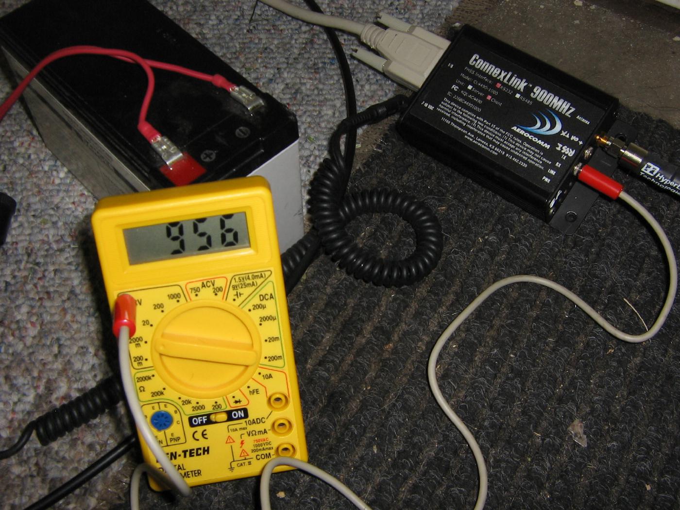
This is the reading with a link established and one of the units is sending a series of "pings." The RSSI value tends to be erratic and will jump around a bit. Also, this may not be very accurate.
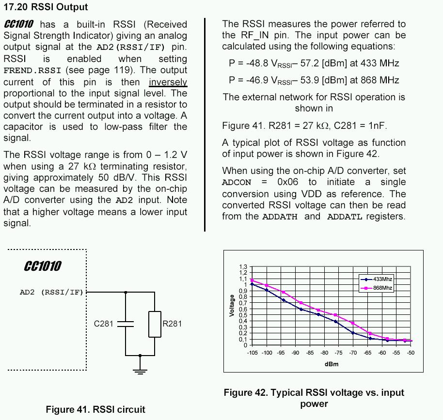
The RSSI value can be converted to a received power level with the following equation:
Recevied Power Level (dBm) = (-47 * Vrssi) - 54
Example: The signal meter is reading "956 millivolts" in the above picture. This corresponds to a received signal power level of approximately -99 dBm.
Experiments & Ideas
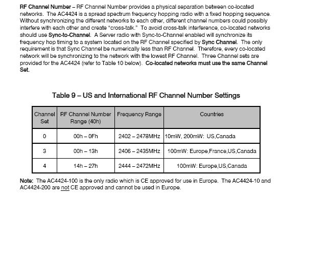
- Downconvert (or modify) the AC4424 2.4 GHz modules into the 430-440 MHz ham band. Adjust the country code to set the frequency range.
- Downconvert (or modify) the non-FHSS AC4486 868 MHz modules down to the 430-440 MHz, or even to the 1.2 GHz or 220 MHz bands.
- You cannot disable frequency hopping, it is a requirement for FCC certification. (AC4424 Frequency Ranges)
- 'setserial /dev/ttyS? spd_vhi'
- Increase "RF Packet Size" at EEPROM offset 0x5B from the default of 0x46 to 0x50.
- Change the "Channel Set" at EEPROM offset 0x40 from 0x10 to 0x00 to only hop between 902-915 MHz, reducing the potential from pager interference
- Enabling "One Beacon Mode" causes the beacon to only be sent once per complete hop cycle. Using this feature can make initial synchronization take slightly longer and can make communications more difficult if operating on the fringe but can increase net throughput. The EEPROM notes also say the "Range Refresh" should be set to 0xFF.
- To set the RF frequency range in the AeroComm AC4424 to hop only in the amateur radio range of 2406 - 2435 MHz, do the following:
"You would select one of the values within the specified range - in that case 0x00-0x13. This single value corresponds to the RF channel number. All RF channels in this range (i.e. 0x00, 0x01, etc) all use the same frequencies; just in a different order. You need to make sure that the channel numbers are set the same on all radios in your network."
- The radios operate on a fixed packet length with timeout. The fixed packet length is 80 bytes. If you send the radio 80 bytes, then it will clear its transmit buffer. The buffer is 256 bytes. If your packets are less than 80 bytes, then the interface timeout will occur between packets and clear the transmit buffer. Packets larger than 80 bytes will get fragmented and you will have to reconstruct at the receiving side.
- On using an analog meter for RSSI (signal strength) indications:
"You could drive an analog meter with the RSSI pin, but it is not recommended. The RSSI tends to fluctuate rapidly and can cause inaccurate results when you are using an analog meter. For the 4424 series, the RSSI pin is the only way to gather RSSI, but due to the way the transceiver calculates the noise floor, we do not recommend customers use it. For the 4490 series you can use Send Data Complete or Receive API and the radios will encapsulate the serial data in a header which contains the RSSI value for when the packet was received. Typically this is more accurate than the pin."
- Aerocomm notes from the TAPR Mailing List:
"The over-the-air baud rate for the 900MHz ConnexLinks is 78K baud. This rate is contant regardless of what the interface baud rate is set at. If you want to use an interface baud rate of 115200, the ConnexLink will have to buffer data in order to run at this speed. If you utilize Hardware Flow Control, ther will not be a problem. Without using Hardware Flow Control you risk overunning the transmit buffers. The ConnexLink compares quite favorably with FreeWave's product. You will get better range out of Freewave's product, but the ConnexLink fairs better when there is in-band interference present."
Notes & Links
These are the original user manuals and configuration files from the old AeroComm website. Updated versions can be found here.
Return to Green Bay Professional Packet Radio for more info and contact information.


