|
N9EWO Review : Yaesu VR-5000 "Wide Band Communications Receiver" |
Discontinued
Receiver
|
VR-5000
Voltage-Current , N9EWO Test / Chart DC "coaxial" plug size used : 5.5
O.D. x 2.1 I.D. Positive "+" tip. |
|
VR-5000
Actual Measured Current
(at 13.0 Volts , Astron RS-7A Regulated Power Supply, Dimmer at 0) (Note : With Dimmer at 7 [max brightness] add 55 ma's to the readings below)
150 KHz : 696 ma
2499 MHz : 738 ma |
|
Included
Unregulated PA-28 AC Power Adapter Voltage
(USA 117 volt version, Dimmer at 0)
Unloaded (not attached to receiver): 18.78 volts
Loaded (receiver on) : 14.09 volts |
VR-5000's
Dual Receive
This is a interesting difference that I have never seen on a
receiver of this type. We have a dual receive system which allows
2 signals to be monitored simultaneously within a 20 MHz spread .
So for shortwave you are covered pretty much. A real stinker here
is that on the sub receiver you may only select the AM (med) and
FM (narrow) modes. So you can have say your favorite Ham SSB
frequency on the main channel and the BBC in the AM mode on the
sub receiver. This generally works well and I found it to be one
of the major "fun" traits of the set. But it does take
a bit getting used to selecting back and forth.
There is a dual tracking function with this system, that is you
can have the sub receiver track automatically as you tune the
"main". This needs to be toggled off as it has no real
use on shortwave.
I was most pleased with this part of the set, great being to
check broadcast "duals" at the same time.
The Spectrum Scope (or as Yaesu - Standard calls it
"The BS - Band Scope" mode)
Yes, we cannot forget the "BS" button on this set....(humm).
This is the other main attraction of this set and can be of use
provided you take the time to really learn how use it, The owners
manual is of little help, missing most of this function. You are
almost on your own.
Not only will it allow you to have a peek at the spectrum in a
given swath (up to 10 MHz), along with various step sizes, and
once you see a signal on the scope you can move a cursor over to
"leap" on to it in a second or two (uses the sub
receiver for this, see manual updates below on how to access).
Again manual was of no help only saying a bit about this part of
the band scope in one of the first pages of the manual. The old
AX-700 / CCR-708 did this operation a bit easier and was and was
"presto" to make happen.
Mind you this is not in any real time, and the more area you wish
to have a peek at the longer it will take for the set to scan
that section and display it. For the amount of money this set
sells for... it works and is another fun part of the set . But
consider it a bit of a rubric's cube....that is you get to figure
it out to an extent ??
It does take a fairly strong signal to show up on the "scope"
display, a signal on the weak side will not show a thing. UPDATE
: 2nd sample was better in this area.
A part of the set I enjoyed with the VR-5000, amazing what
signals I was missing without it.
Unacceptable HF Dynamic Range With Good Antenna, Good
Sensitivity On "Main" Receiver / Too
Much Attenuation
Overall good sensitivity on the main receiver, but the usual
problem with just about all wide-band sets, the the VR-5000
inhibits very poor dynamic range on the HF/SW. Connecting any
large shortwave antenna will overload it for sure and makes it
unacceptable. Even in peak band periods, say 49 meters at night ,
overloading even occurred with a 25 foot thin piece of wire
indoors, near a window.
The set has a one step 20 db attenuator , and of course kicking
it in most of the time helps (not always). With of course
destroying the sensitivity. It would have been nice to have also
seen a 10 db level as well, but adding an external VARIABLE
attenuator helps greatly , see below.
Before selecting the attenuator, a control called "RF TUNE"
should be tried first. This uses the main tuning knob (as does
most of these types of selection functions). You can sometimes
stop the overloading by tuning it OUT of peak , and just maybe
you can tame it without having to turning on the attenuator. It
does not work for me all the time this way..but is worth a try
before attenuation. Good news is that it stores this RF TUNE
value in memory so if you write it to a memory channel..it will
be stored as well as the frequency/mode/tuning step etc.. Bad
news it adds another step to the tuning process in normal tuning
mode.
But really folks......why should a 21st century receiver have
such a fiddly control, but I suspect this comes down to the price
point of the set ? Let's face it...this does indeed stink.....and
the dynamic range stinks even worse. We even tried an external
preselector , will no REAL improvement to the dynamic range..
Even after I get the RF TUNE set right and no overloading on my
shorter 25 ft indoor wire antenna (and peaking it correctly), I'm
still hearing signals where they should not be. Say WWV in the
3900 kHz area. So perhaps a case of spurious signal irking about
??
But if you can live with it, the set seems to work best on
shorter PASSIVE antenna's (thin wire in the room say 25 feet or
less). It clears up some , but not all of the dynamic range
problems on the main receiver. Again I must stress adding an external
VARIABLE attenuator helps greatly with long
outdoor antenna's (see below).
|
I
will NOT be held responsible for any info that is listed here. |
|
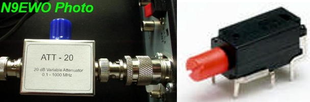
A Way to Tame the VR-5000's Nasty Overloading on HF / SW Bands ? The "Scanner Master" ATT-20 (or build it). |
| The lone
coarse 20 db on board RF attenuator in the VR-5000 provides either too
much OR not enough signal reduction to tame the weak front end with use
on large antennas. Usually it cuts more signal than what is required,
leaving the set "deaf". So to help with this serious drawback one can
add a "External" VARIABLE attenuator. You can purchase one ready made
or provided one is handy with simple electronics and a bit of metal
cabinet work you can build one. Adding a simple external "Variable Attenuator" allows for a much finer adjustment level and does not cut off too much signal , just what is needed to stop the overloading . Placed in the receiver's antenna line externally before the VR-5000's own SO-239 connector. If you need additional "signal reduction" it gives for about 20 db at maximum rotation (pre-made or home-made versions listed below). Select the internal 20-db attenuator and then add additional where needed with a variable one (example: 49 meter band at night). Ready Built : We tested one that came from the USA retail scanner dealer "Scanner Master" and is called the ATT-20. A bit pricey at $ 50. USD plus even more pricey shipping (at the time this report was updated), but works well and can be placed right on the rear of the set. With the VR-5000 one will have to add one RF adapter (PL-259 male to BNC Female, see photo below). It uses BNC connectors. A huge plus to this already build version is that it uses a "Piher Attenuator" . In a nutshell it's a variable resistor that keeps it's impedance stable across the entire tuned range (it tunes 3 pot controls at once). Allows for use right up to the marked range of 1000 MHz. We have tested this and is for real. The homemade version (as covered below) will work near equal in the SW/HF bands , however it becomes very high loss once you get past 150 MHz. A couple of notes : The ATT-20's control turns a bit stiff (in it's 3 turns of rotation). There is a small pointer on the "blue" knob used. This added another bump in the way of rotation (is not the cause of the stiff feeling) , so we just took a pair of nippy cutters and snipped it off as shown in the photo below , this problem fixed . Also don't weight (stress) down the connector on the input of the attenuator with a thick cable (unless you properly support it).
Scanner Master's ATT-20 Variable Attenuator as connected to a Yaesu VR-5000 - (left photo above with required RF adapter) Product uses a Piher Attenuator (right photo above) which retains impedance across it's range. Downsides : It turns a bit STIFF and you also need to snip off the dial pointer on the blue knob (as shown and is easy enough to do). (N9EWO Photo) Or Build One...
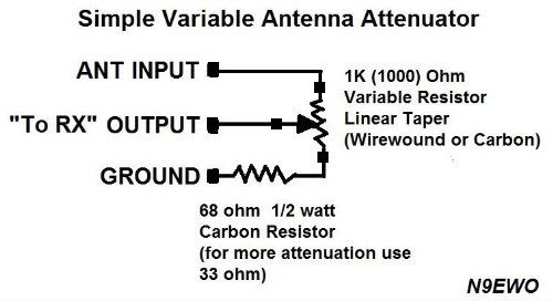
OK for those of you handy with electronics, a 1K (1000 ohm) "linear
taper” potentiometer control is installed inside a small ALL
metal enclosure with the desired RF connectors and knob (all your
choice). The "pot" control is wired with the antenna input on one end,
the ground connection on the other end (note: with a 66 or 33 ohm resistor in
between this ground pin and chassis ground). The center "wiper" is used
for the output to the receiver. Again this control was usable up to
about 150 MHz in testing. I actually used a 10 turn "wire wound type" pot for a
much more precise adjustment, but any standard carbon linear 1K (1000
ohm) will work fine.
© N9EWO ver 4.2 |
Sub
Receiver
at Sub-Performance (tad worse than the main receiver)
The "sub" receiver has a even less dynamic range vs the
"main". It also has a slightly less sensitivity and a
bit less audio level and crispness (as compared to the main).
More background noise mixed in as well. It certainly is not the
of the same league as the "main".
Actually this "sub" receiver is used for the spectrum
display while in the BS mode , so the "Sub" receiver.....actually
using it for listening is a real secondary use and can throw it
in the category "might as well use it while it's there"
.
But it can indeed be of use, as long as you know its limitations.
Dreadful
Owners Manual
As with my comment above the owners manual lacks any important
information, other than the very basic operations of the set. Be
prepared to spend many hours "Trying" to figure out
operations. This has to be one the worst owners manuals I have
ever tried to tackle (expect for the Uniden BC-898T scanner, that's
even worse), ARRRGH !!! Update : The last version of the manual (2009),
is SLIGHTLY better.
Generally Good SSB Performance, No Synchronous Detection
and Poor Manual ECSS
This was a bit of a surprise. The SSB modes have a good bandwidth
being used, true offset filtering, clean sound and proper tuning
steps as well. We can tune as fine as 20 Hz, which is very good
on a set of this type. As I will cover later too, frequency
display is off a bit, as much as 320 hz on USB (LSB not as bad).
But a couple more bug-a-boos.
First the AGC is not adjustable, and the SSB mode's AGC rate is a
bit too fast for my ears. AM AGC decay actually sounds very good
to me.
It lack's synchronous detection (a shame with any set being made
today), and when ECSS is attempted manually it just does not work
right. We certainly can tune fine enough which you would think is
the # 1 problem. It has to do with a heavy amount of a "whoosh"
background noise, like it almost covers it up (excessive phase
noise??). You need to turn up the volume almost all the way to
hear any signal at all. In any case the signal is awash with this
background noise , making manual ECSS unusable.
Good Filter Selection / "Merry-Go-Round"
selection
SSB (LSB/USB) modes have one filter selection so is not
selectable independent of mode.
The AM mode has 3 excellent bandwidth selections in the main
receiver (but you have to get on the carousel-merry go round),
with the widest one being useful for MW or SW broadcasters that
are in the clear (but gives for really nice audio). Again in the sub band you only have AM (med)
and FM (narrow) available.
One mode is tied with a "Auto Step" function. So if you
breeze buy the mode you want, it will take another 8 pushes to
get around to it again (that is if you want a manual set tuning
step). Another ergonomic nightmare with the set.
The manual tuning "Step" button also uses the "merry-go-round"
system.
Hissy
Audio (tone control at full clockwise rotation) / Line Out for
"Main" only and No Squelch
The VR-5000's general audio is very pleasing with a tone control.
However the set's internal audio amplifier is loaded with hiss in
any mode. This is of course noticeable with the volume turned down,
or squelched. Tone control is at a fully "clockwise"
rotation for me (this is where I like to keep it at). The more
you adjust the tone control "counter-clockwise" (to the
left) the less this hiss problem exists.
Even more noticeable with external speakers , but if one chooses
to use the "bottom" mounted internal, it may not be
noticed hardly at all.
If one is a handy, the audio "line" output does not
contain this hiss and could be routed into a external audio amplifier
or perhaps a computer amplified speaker ?? But as noted
below, the "line" output is a bit weak and might not
work properly with some amps. Again, remember the squelch control
does NOT operate in the "line out"
audio (its always open) and also the "sub receiver""
audio does NOT appear in the line output at all.
Line Output A Bit Weak
Speaking of the "line output" , its a 1/8 inch phone
jack on the rear cabinet (where it belongs). It lacks
the standard level that will work with PROPERLY with consumer
cassette or Mini Disc decks. It's a bit on the weak side for sure.
If the station is broadcasting at a proper modulation level ,I
was able to adjust the recorder(s) to a proper VU level, but the
control on the the deck to almost maximum. If the station has
weaker audio, then it's going to be a major problem. We added a microphone preamp to boost the REC level for use on all
signals going to the audio recorders and other audio line devices.
Frequency Display A Bit Off / Runs Almost Hot !!!
On our sample I see a display error of about 320 Hz high (USB
Mode after warm up, LSB Off about 120 Hz high). You would think
that it could be a bit closer here. With the second sample it was
much closer (at about 40 to 70 hz off warm).
After a few hours on at 13.0 volts (Astron RS-7A with a internal
voltage adjustment), the cabinet and even the included PA-28
power supply (if used) gets very warm if not even hot. It's not
heat that makes the set difficult to touch, but more than what I
would like to feel emitting from a receiver cabinet. Cabinet heat
is greater with the PA-28 in use (and more heat stress because of the
higher voltage).
5-Segment Signal Strength Meter
A 5 segment meter can be found for each receiver, and for general
use and to peak the RF TUNE function, works OK. But it is a bit
less than what I would like to see.
There is a way to toggle a meter with more segments using a
function called "Base Field Strength" in the special
modes menu. This gives you a wider scale meter, however it lacks
any markings so is of little real use (cannot use it with the RF
Tune control either) . It's chore to get to and out of this mode.
Good FM Broadcast Selectivity. Sensitivity
I found the VR-5000's FM to be a bit above average. I'm able to
separate stations close together on a lesser set would get washed
out (say the Sony ICF-2010). Sensitivity is also in the above
average category. Yes, it too is prone to overloading with any
real antenna so watch out.
Needs External Speaker
The VR-5000 really needs a external speaker (as does most sets ).
Internal not only being on the bottom, but is bassy and muffled.
The downside is you are going to notice the sets nasty excessive
hiss. Even with the hiss issue an external speaker is a big plus.
Audio Wave Meter
The "audio wave" meter is nothing more than a joke to
me. Looks nice...but of no real use.
No Back Of the Set Antenna's : Extremely Noisy
Microprocessors
If you are thinking of using a back of a set antenna like say
with a Uniden scanner, think again. The radio emits so much
garbage from the internal (2) microprocessors to make it TOTALLY
useless in the approx 30 to 300 Mhz range. This is a MAJOR
drawback for sure to me. In the upper limits it's not as bad, but
this should not be at all. If you need to use an indoor antenna ,
feed whatever homebrew antenna with coax to get it a distance
away from the set.
Known LCD Failures Over The Years / More "sandy" cabinet
finish on Later Samples
Another bug one needs to keep in mind with any used sample is
with the LCD (display) . There have been many
reports over the years where vertical parts (of the dot matrix
sections) drop out, that is go missing. This CAN (but not always)
be caused by bad or dirty "ribbon cable" connections (it does NOT use a
rubber zebra strip ??) or worst case is just a bad LCD. My gut feeling
is this is
a heat stress related failure of the LCD. Again use a Astron RS-7A
regulated power supply with
the voltage set at 13.0 v (internal voltage adjustment control)
for a bit lower heat stress. Also (very important) allow plenty of
ventilation around the cabinet and don't stack ANYTHING around or on
top of it.
The "tacked
on" cordless phone rechargeable battery (except for very early samples)
might need replacing
as well in time ?? Take note : If it gets really bad (like the cells
near shorting out) you could indeed have nasty operational issues
(but this is unknown) !
Later samples cabinet paint have a more "sandy"
feeling finish. Sorry.....it is unknown when this change was
made in production.
Experiencing Dead HF Reception ......"Q2045" (maybe?)
Are you experiencing DEAD or near DEAD HF / SW reception on your VR-5000 ?? A very common failure is MES FET transistor Q2045 (3SK228). Function is the RF amplifier for the 0.1 to 30 Mhz reception which comes AFTER the 5 low frequency filters. This is a 4 lead surface mounted device (SMD) transistor. Yes for those who do not properly physically disconnect outdoor antennas whenever the set is NOT being used (and that is ALWAYS), or for amateur radio folks who uses excessive RF around it and not dealing with it properly, will more than likely experience this failure sooner or later. So you have been WARNED !!
A Very
"Fun" Package For The Wide Band Person, For
"Short Wave" Use (or build) a Variable Attenuator.
Even with its below-par RF performance (sour dynamic range), the
Yaesu -Standard VR-5000 is still a very fun package to play with
having "Dual Receive" and "Band Scope". The
well chosen bandwidth filters makes the audio very tolerable and
generally pleasant. Certainly better than with other sets around
today that might give you 1 poorly chosen one for the AM mode. A
good synchronous detector would have made it even better.
The VR-5000 was a very usable "wide band" set for the
money, but I wish the display was better and more evenly lit, had
better dynamic range, and the excessive audio hiss emitting from
it's audio was not there. Using the "variable attenuator"
(as covered in the above text) helps greatly to make the set
very good on the SW / HF bands .
Dave N9EWO
© N9EWO, all rights reserved
ver 10.2
Discontinued
Receiver
| VR-5000 Computer
Software from Bob Freeth G4HFQ |
|
| There
are very limited choices for ANY computer software with the Yaesu
VR-5000. A few floating around that are not worth your time. However Bob Freeth G4HFQ in the UK comes
to the rescue with a very useful and bug free program called FTBVR5K
for
Windows PC folks (sorry don't know of any for Mac users) as long as you
carefully follow instructions. Is also is now Freeware (was around $ 20. USD). We tested using
Windows XP and Windows 7
(32 and 64 bit versions) with no problems. Says it operates / tested
with Windows XP, Windows Vista, Windows 7, Windows 8 and Windows 10. It
will not run on Windows 8 RT version which does not support desktop
applications. One needs to keep in mind that the VR-5000 computer port (OK Yaesu's term "C.A.T.") uses a good old fashioned 9 pin SERIAL connection. Add on serial cards (for large home computers) can still be purchased today in PCI or PCI express plug in cards. There are also those Serial to USB dongle things (but those not tested by me). Additionally it uses a MALE connector on the radio end just like with any serial connector on the hosts computer serial card end. So one needs to use the odd FEMALE to FEMALE 9 pin serial cable or the use of a "gender changer" adapter on one end. One VERY IMPORTANT note, you will also need to make use of a NULL MODEM adapter or cable. Otherwise no software is going to work with the VR-5000. FTBVR5K - "Memory Management" programming software for the Yaesu VR-5000 receiver. Yes, a MUCH better way to program the memory channels including the alpha information. We have found no equal to this simple but excellent (and now freeware) program. Download page here.
|
|
VR-5000
corrections and updates to the manual May no longer be valid depending on firmware version and version of manual. |
Page
3
(6) Function Keys
[BS(BS SET)] Key
Press this key momentarily to toggle the Band Scope feature on
and off.
Press this key twice, after the [F] key is pressed (when the Band
Scope is activated) to activate the SUB VFO cursor, which enables
the SUB VFO tuning.
After you've activated the Band Scope, press the M/S key, then
press the [F] key, then press the [BS(BS SET] key twice. You
will now be able to move the channel marker within the sweep
range as programmed.
Set the Channel Marker to the desired position (frequency); now
press the [COPY] key. The SUB VFO frequency will move to the new
position you set (the current location of the Channel Marker),
and you'll hear the new channel's activity if you have the SUB
VFO volume turned up. If you now press the [BS(BS SET)] key, you
will see that the SUB VFO has moved to the Channel Marker's
frequency, as both VFO frequencies will be displayed.
Pressing the [BS(BS SET] key once more will restore the Band
Scope display.
Page
37
Under "To
Activate the Band Scope ..."
3. When the Band Scope is activated, press the [M/S] key; you can
now move the Channel Marker. This allows the Channel Marker to be
moved anywhere within the programmed sweep range. When the
Channel Marker is set to a frequency that may be of interest,
press the [COPY] key; the frequency will change to that set by
the Channel Marker.
| "Yaesu" USA Press Release |
More
"VR-5000"
manual corrections.
Programmable (Band
Limit) Memory Scan (PMS)
This feature, a more refined and useful form of VFO scanning,
allows you to establish sub-band limits for scanning. This allows
you to monitor only a portion of the wide frequency range of the
VR-5000, instead of sweeping the entire spectrum from 100 kHz to
2.6 GHz. Programmable Memory Scan utilizes a pair of frequencies
to establish the upper and lower scanning limits within special
memories. Here is the procedure for setting up limited band
scanning:
Programming
1. Press the [F] key momentarily, then press the [PMS(PMS SET)]
key to enable the storage of the frequency pair into a PMS memory.
2. The cursor will be pointing at the PMS CH menu option; press
the [ENT(SET)] key.
3. If you want to program the frequency pair into the
currently-selected
PMS register (shown on the right edge of the display), proceed to
the next step; if you wish to choose a different PMS register,
press [ENT(SET)], then use the [q(t)/p(u)] keys to select a
different memory register number. Then press [ENT(SET)] to move
on to the next step.
4. Rotate the DIAL knob to set the cursor to the PMS TAG menu
option.
5. Press the [ENT(SET)] key to enable the programming of the name
tag to the PMS memory. To attach an alpha/numeric name tag to the
PMS memory, program the alpha-numeric label using the DIAL knob
and keypad, as described previously; if you don't want to label
this frequency pair register, press the [ENT(SET)] key again.
6. When you have complete the creation of the label, press the
[ENT(SET)]
key.
7. Now it's time to set up the band limits. Rotate the DIAL knob
to set the cursor to the START F menu option, then press the [ENT(SET)]
key.
8. Set the VFO frequency to the Lower sub-band limit, then press
the [ENT(SET)] key.If you programmed the frequency using the
keypad, press the [ENT(SET)] key again.
9. Confirm that the cursor is on the END F menu, then press the
[ENT(SET)]
key.
10. Set the VFO frequency to the Upper sub-band limit, then press
the [ENT(SET)] key.If you programmed the frequency using the
keypad, press the [ENT(SET)] key again. 11 Rotate the DIAL knob to set the cursor to the END menu option,
then press the [ENT(SET)] key.
12. Confirm that the cursor is on the WRITE menu option, press
the [ENT(SET)] key.
13. The PMS memory programming process for this register is now
completed.
Note: 50 PMS memories are available. You therefore can set upper
and lower operation limits on a number of bands, if you like.
Each PMS memory register, remember, stores both the lower and
upper frequency limits.
Operation (Current PMS Register)
1 Press the [PMS(PMS SET)] key to initiate PMS scanning in an
upward direction.
2. If the scanner encounters a signal strong enough to open the
squelch, the scanner will halt and pause on that frequency.
Scanning will resume according to the protocol you selected in
the previous discussion.
3. To change to a different PMS frequency pair, press the
numerical keys on the keypad corresponding to the PMS register
you wish to use. For example, if you are on PMS register and wish
to use PMS register 03 press [0] + [3] while PMS scanning is
engaged. Scanning will begin on the new register without further
action.
4. To reverse the direction of the scan (i.e. toward a lower
frequency, instead of a higher frequency), turn the DIAL knob one
click in the counter-clock direction or press the [q(t)] key
momentarily while the VR-5000 is scanning. To revert to scanning
toward a higher frequency once more, rotate the DIAL knob one
click clockwise or press the [p(u)] key momentarily.
5. Press the [V/M(MW)] key to disable the PMS scanner, and return
to VFO mode.
|
Comments From Others |
VR-5000 MEMORY BANKS
AND
STORAGE
While in vfo mode, to store the current vfo frequency into memory,
hit "F-V/M". At this point, the cursor will be pointing
to "Channel".
Hit "Enter". This brings you to a page with the
frequency displayed, and the bank will indicate "00",
and the "ch" number will be one more than the highest
channel existing in bank 00. It has temporarily created a new
channel in bank 00 for you to store the new frequency in.
Assuming, however, that you don't want the frequency stored in
bank 00, hit the "v ^ " (arrow keys to left of dial) to
choose one of the existing banks. Using the arrow keys, you can
access ANY EXISTING BANK PLUS A NEW BANK.
This is the point that confuses people. It is not possible to
select any bank number at random, but only one new bank. For
example, if you have banks 0 to 5 already defined, then when
you go to store a new frequency, it gives you the option of
storing the frequency into any of those banks, or you can choose
to store the frequency in a new bank 6. If you have 0 to 6
defined, you will be given the choice of storing in a new bank 7,
etc, etc, etc. You can create as many banks as you want, but you
can only access them one at a time.
If you want to have dozens of banks to choose from, then all you
need to do is to store some dummy frequency is each bank you want,
one by one. When you go to actually put real frequencies in those
banks, just choose the channel number of the dummy frequency
before you store your real frequency.
After you have chosen a bank, choose the proper channel number,
either an existing channel or the one new channel number, and
then hit "enter". This brings you back to the previous
page, with the cursor on "CH TAG". At this point, you
can store the frequency by turning the tuning knob down to "END",
and hit "ENTER", which brings you to a page with the
cursor on "WRITE". If you hit enter now, it will store
the frequency. If you have made a mistake, you can tune down to
"CANCEL", and choose that option.
When on CH TAG above, you can enter a name for your channel if
you want, or you can come back later and edit that item. Once a
frequency has been stored in a bank, if you select that bank
while in memory mode (V/M) , you can enter a BANK name, and some
other features, by hitting the BANK button. Again, edit the items
you want to change, then tune down to END, and WRITE the data.
One additional item of confusion, is that some of the functions
you try to alter using the above method (I can't remember which
ones off hand, but that isn't important), don't seem to respond
to the "ent" key. If you try to change a value, but the
enter key doesn't seem to work. If that happens, the secret is to
use the " ." (point) button.
The entering of frequencies into this receiver is really quite
simple once you get the hang of it. It's just that the procedure
isn't explained very well in the manual, and often the manual is
just plain wrong.
One other comment: I have used the "ent" key in my step
by step above, whereas the manual describes the use of the copy/rec
key in some cases. I know that the copy/rec key works the same in
some cases, and is a shortcut to getting down to the end/write
options, however I think it is easier to understand if you scroll
down to those items and use the enter key instead.
Bill Jones N3JLQ
(sorry, from unknown
sources)
VR-5000
PRIORITY
MONITORING
First, in memory mode, select the channel you want. Then follow
the instruction below.
To setup the Priority Monitoring:
1. Press the [F] key momentarily, then press the [V/M(MW)] key.
2. Rotate the DIAL knob to select the cursor to the "Channel"
menu, then press the [ENT(SET)] key.
3. Press the [F] key momentarily, then press the [5(PRI)] key. A
"PRIu" icon appears on left of the memory channel
number in the LCD. Then press the [ENT(SET)] key.
4. Rotate the DIAL knob to select the cursor to the "END"
menu, then press the [ENT(SET)] key.
5. Confirm that the cursor is on the "WRITE" menu, then
press the [ENT(SET)] key.
MISC.
SCOP save option: Sets the
time the bandscope picture is kept in memory when the BS key is
toggled on and off.
In this case you can keep in memory (if set to infinite) the last
snapshot of the bandscope before it was toggled off. Of course,
as soon as the bandscope is activated again, another band sweep
will start, deleting the old picture saved in memory.
Func TM Timer: sets the time
the F mode is active (when the F key is pressed and the F icon is
on) before it goes off.
Skip
Data: Skips data
transmission channels (e.g. GSM carriers) in autostore mode. In
my case it works as well as the autostore (1u.17)
It is fairly easy to change the parameters of a stored channel. A
memory position, once recalled and having some parameters changed
(e.g. RF tune, step size, mode) can be saved again by pressing F+MW
then, at the next prompt, twice the COPY button.
SERIAL NUMBERS
Yaesu - Standard uses the same serial number scheme for all of
their ham gear. The serial number has the form YMLLNNN where Y =
the last digit of the year of manufacture, M is a letter
representing the month of manufacture with "C" =
January, "D" = February, and so on, the lot number is
represented by the two digit LL (00 - 99), and NNNN (0001-9999)
is the unit number within lot LL.
As an example, 0N070145 means December 2000, lot 7, unit 145. The
lot number is not linked to the year & month, i.e., LL does
not reset to 00 each year. Service bulletins refer to lot numbers.
Another Example: Serial number 1e110089 means:
Manufactured: March 2001
Lot (production run) : 11
Unit: 89
TRICKS with the
VR-5000 (N9EWO)
1. Holding the V/M button down while powering up with
the VR-5000 you will see the Firmware Version #.
2. Holding the 'Dim' button while powering up the unit on , you
get a test screen with all the LCD icons (sic) showing
up.
NOTE: These 2 tricks will NOT work on firmware
versions above "1u.17" .