| N9EWO
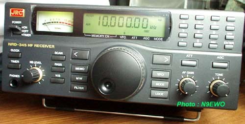
Review : JRC "Japan Radio Co." NRD-345 HF Receiver |
(Discontinued
Receiver)
The JRC NRD-345, Now a Rare Bird on the
Used Market. AOR Japan ??
The now rare discontinued " Japan Radio Co. NRD-345 "
had a short life on the market. With the data I have, it was in
the JRC active line-up (made in Japan of course) between late
April 1997 to April 2000. Actual REAL production
dates I remember were much shorter than this (more like early-mid
1999 ?.
J.N. from Japan reported to me some time back that the NRD-345
was NOT manufactured by JRC. He says that it was made for them by
AOR Co. Japan. However I do not have any solid information on
this and we may never know the real truth on this one ? I do not
think this rumor has any real truth to it.
General Stuff including 2 VFO's. Meter Lamp In A Socket.
Dual Up-conversion. The NRD-345 uses a 1st IF of 44.850
Mhz. The normal JRC 1st IF is 70.455 Mhz. If you
take a GOOD look at AOR's old AR3030 receiver, the general
software buttons/general operation are quite similar I will admit.
Even the IF frequencies are identical.
Real HF coverage is from 10 kHz to 30 Mhz. 1st mixer uses 4 FET's
(just as it is with the JRC NRD-535 and NRD-545). One IC DDS (Direct
Digital Synthesizer), that allows down to 5 hz tuning steps.
Tuning knob is very smooth and uses a rubber track around the
knob, it the right size along with being properly weighted and
uses a excellent optical encoder. The general feel of the
knob doesn't get any better than this , even if it lacks any
"feel" adjustment. The only real downer here to me is
that it lacks 5 Khz steps either with the tuning knob or the up-down
slewing buttons. So one has to make do with 1 KHz steps for
general tuning around the SWBC bands.
2 VFO's and a real tilt bail with protective rubber tubes on this
and real rubber feet on the rear as well. This is the only JRC
RECEIVER to ever offer 2 VFO's or the tilt bail. I never knew how
useful having 2 VFO's really was. Why this was never offered on
other JRC receivers is a row of question marks ??
A solid steel cabinet as with all other JRC receivers. This is
far better over the AOR AR7030's soft metal cabinet to me. We
have an internal speaker, but as is the case with most tabletop
sets it's pretty much worthless for any real listening (more on
this later). Excellent front end filtering, image rejection,
sensitivity/selectivity. All buttons have a very good feel and do
not use any rubber or rubberish buttons, and support a solid feel.
All are hard plastic and use tac switches. The downside is as
just like on the NRD-545 most buttons are painted, and are prone
to show wear with any real use. Here is a switch : The rear
mounted external speaker and line output jacks are using 3.5 mm (1/8
inch) "Phone Jacks" , not the RCA phono type as with
ALL other JRC receivers.
You can enter frequencies on it's keyboard as Khz or Mhz, or even
punching in the direct "meter band" numbers. It's so
easy to use and no second function with the buttons (a few minor
exceptions one being with the tuning steps, but this was done
right). 100 memory channels which works OK for me, but many would
find this to be a real drawback. Still uses a DB25 serial
connector for use with a personal computer (RS232), and yes it requires
a null model adapter or cable just like all other JRC sets
that can be connected this way.
This is one extremely easy to use HF receiver, the ergonomics are
first rate.
LCD is properly lit with LED's with perfect contrast to boot.
The meter is lit using a 6.3 volt 150 ma lamp. A bayonet SOCKET
is used and not just direct wired in. This is so rare these days
to see a socket used with any panel lamps ! It burns on the dim
side too, so it should not require replacement too often.
Included NBB-429 USA Power Supply Is A Good One, Improved
The Transformer Buzz.
The Japanese made external NBB-429 117vac power supply's
transformer at first made a pretty bad buzzing sound within the
room (output is very clean). Also with the first sample tested
back in 1997, when the volume was turned up (loaded down), the
panel lamp and LCD backlight dimmed with the audio peaks. However,
I did not experience this bug with the sample I used for this
report (it was from later production).
Important Tip : Be sure and keep the s-meter light bulb
contacts and socket clean, more so with the solder "tip"
on the bulb. If this is not done the LCD backlighting and S-meter
lamp can still indeed dim with audio peaks !! Oddly the LCD
backlighting (LED's) and the meter lamp are wired in series.
It turned out that the buzz was caused with the internal power
transformer not being properly seated in the 2 grooves in the
bottom of the plastic case (it pops in quite hard). Once this was
done, this buzz issue was down to a improved level even under
normal load. However it was never as quiet as one might hope for.
Better yet, unlike the Yaesu FRG-100 (and others), this is a
"regulated power supply" floor wart and is rated
at a 800ma output. It uses a 12 volt Sankyo SI-3122V linear 2 amp
IC regulator on a large heatsink, which is all good news (the
3122 is in a TO-3P package). 4 bypass disc
ceramic capacitors are provided across the bridge rectifier block
as well to tame any switching noise from these diodes. 2 actual
screws hold it together (not just glued together).
A very stiff 3 wire cord is used and the ground "green wire"
from the power cable is connected to the ground on the power
supply PC board. So a word of warning here if you have any "audio"
ground loop issues as this could make it worse. This power supply
runs a bit warm if not near hot when used for awhile. The
receiver however runs very cool, even being on for hours.
2 Line
Output
Jacks, not 2 in the same however. Either fixed "audio output"
has distortion to my ears on SSB modes.
On the rear of the NRD-345 we find two 1/8 inch (3.5mm)
phone jacks for a "line" audio output. This type of
jack being used here is strange for JRC as on all other consumer
models this has always been RCA-phone jacks. But it gets a bit
more weird.
These jacks are marked as FAX (line out) and the other as RECORD.
The FAX (line out) jack is at a perfect level for input to a
consumer recording device or connection to another amplifier or
even
amplified speakers. The RECORD jack is at a very low level and is
good for direct connection to a MICROPHONE jack on a tape
recorder. This RECORD jack sees a 22K resistor in series and
after than a 680 ohm in parallel (attenuation) vs. the
FAX one. They do indeed share the same buffered fixed audio
output. Additionally there is no way to adjust the output of
either of these (no internal level control at all).
Sadly, we discovered an annoying amount of audio distortion from
either the lower level RECORD or the higher level FAX (line out)
jacks on SSB modes. For most users this may not be an issue (who
cares right ?). But as I make serious recordings from a
receiver, it was a no go here I'm afraid for me.
Audio Quality is OK, So-So Sync.
Using the narrow AM mode "Wide" IF filter,
audio quality suffers as it lacks any high end audio frequencies.
One can tune off a Khz or 2 and improve this a bit without adding
too much distortion (it does not to my ears anyway). SSB modes
par much better and overall I feel is better over the AR7030
for any quality listening to SSB stations. Manual ECSS works
EXCELLENT as long as the station is on top of the 5 Hz tuning
steps, additionally there is no hiss at all. After connecting to
a stereo receiver amplifier
, I noticed a bit more
bass response that
you don't normally hear with a communications receiver (however
see the SSB "line out" distortion issue above). If this
is a plus is going to be personal thing but is the most bass I
have even heard to come out of a JRC receiver.
Just as we have experienced back in 1997 with a sample
we had a chance to play with briefly, the "double sideband"
only Sync Detection is so-so at best. It can actually add a bit
more distortion depending on the signal. But on the other side of
the coin, once in awhile it can help to reduce fading distortion
(again depending on the signal). But overall it was not useful to
my ears.
External Speaker a Requirement, Rated 8 Ohms (not the usual JRC 4),
No Muting Function for Use With a Transmitter, Missing Squelch
Control.
As it is with most tabletop sets a GOOD external speaker
is a must. This is even more important with the NRD-345. The
internal speaker is downright awlful. I will say choose one that
does not give added bass response as that will make the "woofy"
sound even worse. With all other JRC sets I have touched over the
years the speaker rating is at a 4 ohm load. Not so with the 345,
it's rating is at 8 ohms.
Lots of punch to the audio, so one does not have to worry about a
whimpy output here. If one fully turns down the
volume control, I was able to hear some audio left anyway more so
in a totally quiet room. Again, I must stress
the the distortion issue with the Record and FAX outputs as
covered above, if that is important to you.
The volume control not is microprocessor controlled like
with the NRD-545. It's adjusted via the good old fashioned analog
method.
There is no "Mute" function or squelch, but I
did not find either of these missing to be a drawback.
Feedback "Beep" Too Loud For My Taste, Owners Manual
Has Typo For "Frequency Reference Adjustment" On Page
25.
As it was with the NRD-535 and yes even with the NRD-545
the keyboard feedback "Beep" was much to loud out of
the box for my tastes. But as with the other JRC sets, there is a
way to adjust this volume or to just shut the beep off. However,
I would like to have some keyboard feedback just not this loud.
In the case of the NRD-345 for adjustment of this this level is
done with the internal trimmer resistor
RV7. This is located on the "bottom" CAE-368
board on the rear edge in between the FAX jack and the DB-25
computer port. It is very well marked on the board (you can't
miss it).
For any slight frequency display errors, the reference oscillator
trimmer capacitor can be tweaked. I will say after a 3 HOUR
warmup with the cover(s) on. This internal CV3 trimmer capacitor
is found on the "top" CMA-648 board, where the
control is also located along the rear edge under a metal cover.
Page 25 of the owners manual indicates this trimmer is marked as
CV0, well this is a downright typo. No such thing as a CV0 even
in the receiver at least on this 2nd test sample. I would use WWV
at 15 Mhz to do this, USB mode with the widest bandwidth filer.
As it goes with these type of adjustments, the higher you go in
frequency the more touchy this is. So if it's off at 10 Mhz, it
will really be off at 15 Mhz as so on as you go up. CV3 is also
well marked once the little metal cover is removed (it just pops
off).
I must pass along the usual WARNING here. This is a very
touchy thing to get right and may take many attempts. Pass on
this one if you are not good with these sort of adjustments. Also
being this is NOT a high stability type of crystal being used
here (and never was an option for such), you may never get it to
stay quite "dead" on. It might be 1 or 2 Hz
off anyway you slice it depending on room temp. But this is not a
drawback at this price point to me and actually has excellent
stability.
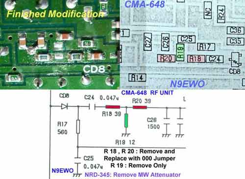
20 db MW Attenuator (but can this can be removed ?)
|
I
will NOT be held responsible for any info that is listed here. |
This receiver uses
a
"extra" attenuator in the MW band to help deal with
dynamic range. Is not to be be confused with the regular ATT
function (not the same beast).
Looking at page 12 of the NRD-345's "Service Manual",
it indicates an additional "20 db ATT" with the low
pass filter on the MW band between 540 Khz to 1.8 Mhz. If you
want to see the change with it bypassed (without doing any
modifications at all), tune between 539 Khz and 540 Khz. Boom,
you can see how much signal is actually lost.
As many already know this additional 20 db attenuator is not
defeated with a button press either. One who is handy with
surface mount electronics should be able to remove the 3 SMD
parts on the top CMA-648 board ,and install the required 2 zero
ohm (000) SMD jumpers of the right size. However, I have NOT done
this (and don't plan to) and if you mess up or this information
is bunk, it's YOUR problem. See the picture below. The finished
modification photo below was NOT taken by me (this
picture source unknown).
|
I
will NOT be held responsible for any info that is listed here. |
Needs
additional wider voice bandwidth filter, adding
a "Defacto"
one to the "AUX" spot using the CFQ-8673 option board ?
The NRD-345 desperately needs an additional wider filter for AM
mode signals to help with audio quality when one could use it.
There is a option for another filter using the CFQ-8673 plug in
option board. However this is made to work with JRC (NTK) huge
crystal filters that are were all on the narrow side anyway, so
again useless.
Optional service manual does not give details of the CFQ-8673
"Aux filter board option" components or values of those
components (not even a simple schematic). On this board there is
a series variable coil , a SMD series capacitor and one more SMD
capacitor connected in parallel , all repeated on the other side
of the filter board.
Looking back at the schematics from the NRD-525 and 535, JRC
provided a "Defacto" super wide filter if one
did not install the optional filter(s). This was actually no
filter at all and was bypassed using a jumper for a nice wide
filter setting.
So I was thinking why not do this with a the open AUX spot on the
NRD-345 (using the CFQ-8673 Aux board to make it easy) ? However,
unlike the older NRD-525 and 535 models, the 345 uses a 6 Khz
"IF Tail Filter" at the end of the IF chain (but
measures more like 7 to 8 Khz). Why even bother with a filter for
a wider bandwidth anyway with this tail filter in the chain.
Following the idea from the NRD-525/535, I went ahead and did the
modifications to the CFQ-8673 plug in board and it
worked 100 % perfect. For the details on how I did this see the
picture below. It requires the "techie person" to
remove all of the SMD capacitors and coils on the CFQ-8673 board
and then adding 3 jumper wires and 2 SMD 000 jumpers. Mind you
this only adds a couple of Khz of bandwidth (perhaps up to 7 to 8
Khz ?), but with the case of the NRD-345, this really does help
with the audio in the AM mode. It can be pulled out in a flash of
course and no modifications to the actual receiver at all.
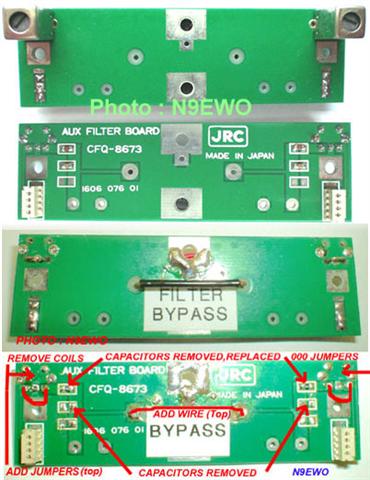
Before (top 2) and After (bottom 2) Pictures Retro-Fit of
the CFQ-8673 "Aux Filter Board Option"
See text above for more information. Sorry, I will be unable to
do any retro work.
(retro-fit
and photo's : N9EWO)
|
I
will NOT be held responsible for any info that is listed here. |
A Nice
Receiver Overall.
I feel the JRC NRD-345 is generally a good receiver overall. It's a
more useful set for use with SSB uses (Manual ECSS,Hams,Utes,etc.).
Adding the wider "Defacto" bandwidth using the
CFQ-8673 "Aux Board" does help the audio in the AM mode.
But one needs to be aware of the distortion issue with the Record
and FAX outputs (SSB modes) if you do any serious recording.
Of course one will have to hunt on the used market now as any new
samples of the NRD-345 have been long gone for years.
Dave N9EWO
© N9EWO
Ver. 5.6
(Discontinued
receiver)
| PUSH
AND HOLD AT POWER UP |
JRC NRD-345 "Power Up" User Defined Functions (this chart via n9ewo) |
|
MODE |
Toggles Keyboard "Beep" at Speaker Output (on/off) |
|
mtr |
Resets all "Meter Band" data |
|
FILTER |
Adds "AUX" Filter Selection |
|
CLR |
Initializes VFO and
Other Settings to Factory Defaults (does not clear Memory Channels) |
|
MEMO |
Clears all Memory Channels |
|
AGC |
Adds AGC "OFF" Selection |
JRC NRD-345 English Owners Manual (via manualslib)
JRC NRD-345 Brochure (via KO4BB web site)
JRC Amateur and SWL gear (groups.io)