|
N9EWO Review :
PALSTAR LA30
Ferrite Loopstick Antenna
(prototype)
|
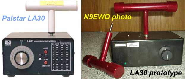
The
very pricey "Palstar LA30" Ferrite Loopstick Antenna on left.
Prototype built in a plastic case on
right.
Both
shown
with the MW loopstick attached.
Laying on left side of the prototype's case is the "tropical
band" element.
(left Palstar photo, right N9EWO photo)
Very
Important Note : The review and information you read below was
done with a PROTOTYPE of the Palstar LA30 Ferrite Loopstick
Antenna,
and may be different when compared to
actual production samples. We have NOT tested a actual production
unit at time of writing (and have no plans to do so).
What's
Up With This Thing ? / High Quality Tuning Capacitor
OK, so I’m not a “Medium Wave DX”
broadcast listener. I may tune casually around the band once in
awhile and that’s about it. However in mid-August of 2008 I
was very fortunate to obtain a prototype of a “Ferrite
Loopstick Antenna” from the RF engineer Pete Gianakopoulos KE9OA
(sadly is now a S.K.) who designed it for Palstar
in Ohio USA. In
the spring of 2009, the model number was decided as the "Palstar
LA30".
IMPORTANT: What I cover here with this prototype
may not be true with any “actual” production sample.
For two, the prototype lacks the power and attenuator buttons. No
internal AA battery holder either. The PC board (at least in the
tested prototype) is of a high quality glass epoxy “shielded”
type. The numbers on the 2 boards shown in the photo below are
slightly different. The RF engineer gave me an "extra"
PC board with no parts on it at the same time as shown in the
picture below. I’m sure that other minor differences exist
too ?
The large and geared tuning capacitor is used in actual
production samples. The one installed in the tested prototype was
smaller, however it's still larger than most caps that are used
in gear today and even has ball bearings. But in either case it
uses a much HIGHER quality capacitor over the now discontinued Quantum
loops,
which contain a tiny and much lower quality
plastic transistor radio tuning cap (for example what you would
find in a cheap $ 2. AM pocket radio ?).
The prototype was built in a large plastic box. Of course the
production units are in a solid all metal case
.
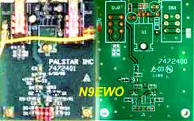
Production Palstar
LA30
"7472401" PC Board w/parts (on left).
Prototype "7472400" PC Board with no parts attached (on
right)
(left
Palstar photo, right N9EWO photo)
Balanced
Loop and FET Amplifier / How Well Does it Work ?
Very high Q and gain, approx. 20 db > area (for the
prototype). Yes, very VERY SHARP tuning. Balanced loop /
amplifier design using two surface mounted MMBF5486 FET’s
followed by a MMBR941 output transistor. However, from viewing
the "on line " owner’s
manual and schematic, production samples use a MMBT5486 output
transistor (or is it a MMBT5179 ?).
The on-board
10-volt
regulator is a nice touch however it was not used in the
prototype (bypassed) for the increased gain. I just have to
remember to use a 12 volt regulated wall wart with it (no
biggie). The web site and owner’s manual specifications list
the gain as 15 db.
Update
: The text shown below in bold (and updated schematic) in a more
current version of the owners manual , points to the internal 10 volt
voltage regulator now being omitted. However this has not been
verified. But all the more reason to use a "non switching" 12.0 volt
regulated power supply with it (and NOT at 13.8 volts). I now have to
wonder IF Palstar ever used the 10 volt voltage regulator as in Pete's
original design from day one ??
"NOTE : Powering the
LA30 with more than 12VDC will cause the audio to distort. We supply a
9VDC wall adapter because at the current draw level of the LA30, its
output is very close to 12VDC. The typical 12VDC wall adapter will have
an output closer to 15VDC, which is too high for proper operation."
The Jameco
170245 regulated 12.0 volt 1 amp "wall wart" supply we use
with the LA30 Prototype and works excellent (extremely clean, entirely
non switching) . WARNING : A caveat
as Jameco has started to use switching regulators in SOME of their
older "linear marked" regulated adapters and with NO model number
change that indicates this change (but
does not affect all of them). We have experienced one of these changed
new
style adapters (was different voltage/model) with the switching
regulator inside , and are unusable with any radio products (very RF
dirty/noisy).
From what I
can tell (with my limited MW loop experience) the
performance / gain is excellent using the MW loop with
equally excellent directivity as it's rotated. With the
PROTOTYPE “Tropical Band” loop, the gain is the same
but with less "sharp" tuning. This can be expected with
the frequencies involved. Rotating it does little to null out
noise/signal again with the higher frequencies. Also the tropical
loop was wound on a slightly shorter ferrite rod over the MW one
(remember : these are prototypes). Additionally I was told that
production samples are using slightly thicker ferrite rods. In
all cases the loops are wound using # 36 x 14 strand
“Litz” type wire. Additionally, these loops do not tilt
in any way and of course the Quantum
ones do.
On ONE very strong 1 kW MW local signal, I had to kick in some
attenuation (or slightly off peak the tuning) to control some
minor "receiver" overload. But this was not a real
issue and the production units have a switchable 15-db-attenuator
button just in case.
This prototype coverage is from 520 to 1700 kHz on the MW loop
element, and from 1700 to 5500 kHz on the Tropical Loop element
(actually
up to 6500 > kHz with reduced performance / gain).
Was
This
Prototype A Winner ?? / Too Expensive
No…. it probably does not work as well as a larger
loop, but considering the size of this antenna, this “prototype”
of the LA30 performed very well indeed to my ears. It
does not require all kinds of room either. If production units
work any differently...…sorry I cannot say, untested as I
type this text. Palstar does seem to have this
loop overpriced in my view, and the LW and Tropical Loops are even
sold separate adding to the already high cost (comes only with
the MW loop).
Dave N9EWO
© N9EWO, all rights reserved
ver. 3.5
To Main Page