|
|
|
Overview |
|
News |
|
Technical Info |
|
Pictures |
|
Mechanical Details |
|
Control System |
|
Cameras |
|
N8MX Home |


Technical Details
|
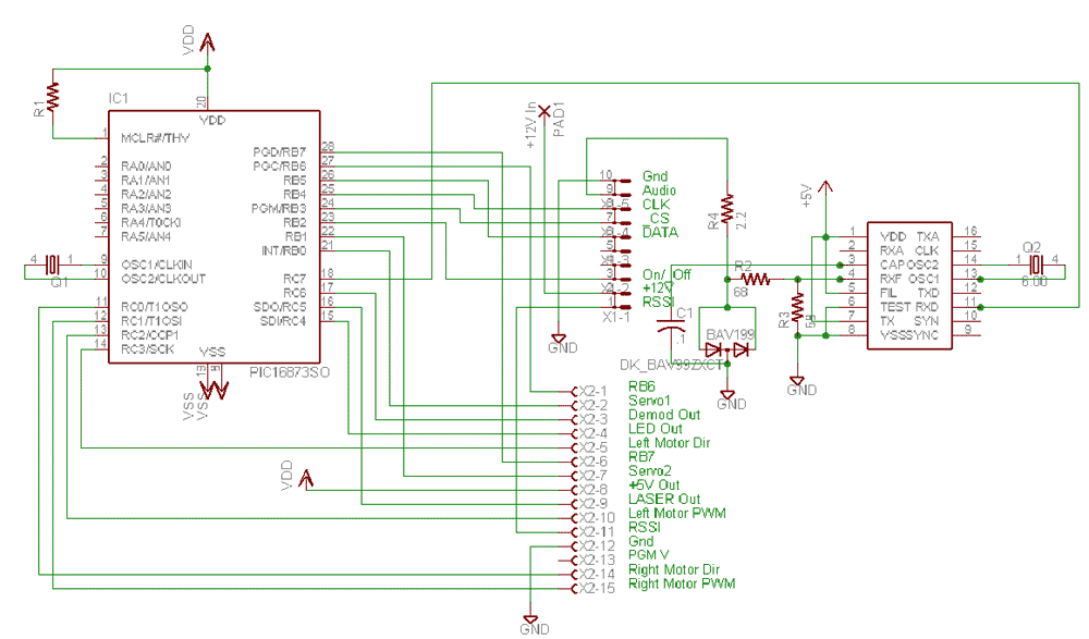
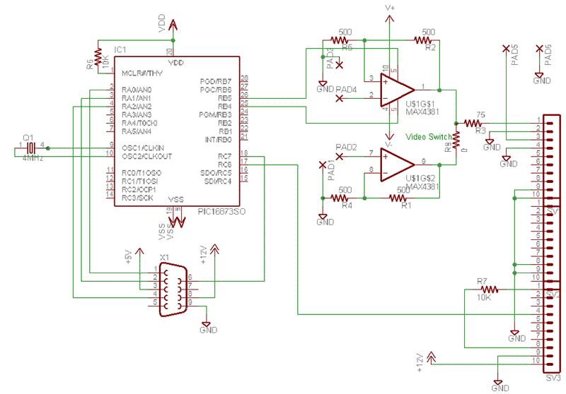
Here is the preliminary schematic for the Main Electronics Unit. The processor mainly interfaces to external modules, with the exception of the onboard modem and radio connector (to later support an integrated radio). (3/31/02) Here is the preliminary schematic for the Video board. The video switch and overlay board are currently the only things on here. The transmitter interface will be added later. (3/31/02)
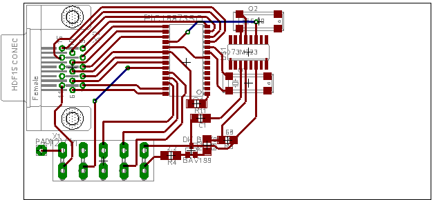
Here is a very preliminary layout for the main electronics unit. I want to see if I can get it all on a single side before we have the first one made. (3/31/02)
Here are some source code (.asm) files for the PICs. I try to do a reasonable job of commenting it, let me know if you would like more info about parts of it or certain parts work. You can use any of the code found here, but I would appreciate an email letting me know that you are using it. I would like to know if I am helping other people out by having it here. The servo controller code was written for a PIC16F872 running at 24.5MHz. I am going to have to slow it down a lot when I move to a slower clock. I had the 24.5MHz crystal in so I thought I may as well use it. This code was written to incorporate into a larger program (which will eventually run on the peripheral controller). The code outputs a pulse that varies in length from .5ms to 2ms long on each of the two servo pins, every 17ms. Everything I have read about servo control says that the servos take a 1-2ms pulse (length dependent on desired position), but I found that the servos I am using (Futaba S3003's) need to get down to .5ms and go to 2ms to reach full throw of the actuators. The first program I wrote used TMR1 (an internal 2-byte hardware timer on the 16F872) set to interrupt every 17ms to time the distance between the pulses, and then used looping delays to accomplish the variable-length pulses. However, since the CPU was needed for the looping, the PIC couldn't do anything else at the same time. I think about 20-30% processor overhead would be needed just to control the servos. The next program is much more elegant and all of the servo control is done within the interrupt service routine using TMR1. A system of bit flags is used to determine which of the timing subroutines is to be executed (either the 17ms delay, or the servo1 or servo2 pulses). For the servo pulses, the position value is multiplied by 6 (I found the multiply routine at www.piclist.com), added to 191 (the initial .5ms pulse required for a position of 0) and then subtracted from 0xFFFF (hex) because the timer counts up instead of down and then interrupts on overflow. This sounds complicated, but seems to work very well. |
[Tank Home] [N8MX Home]
This page last updated 4/7/2002.
© 2002 N8MX.