Build Your Own Transmitting Air Variable Capacitors!
By: David Hammack, N4DFP
|
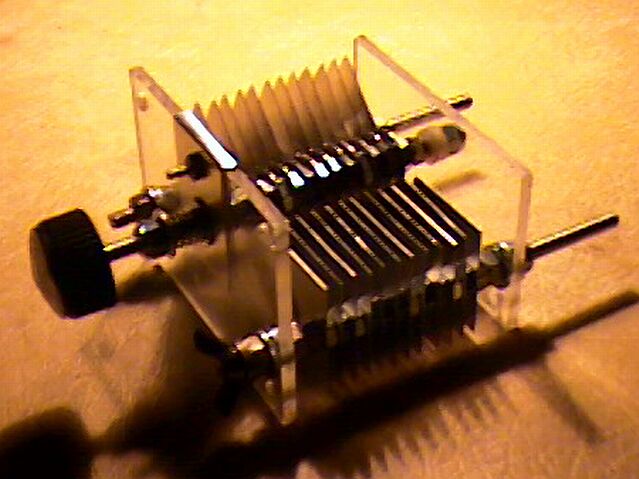
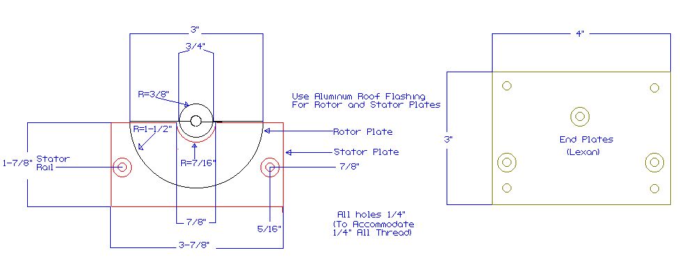
As I was building my transmatch, I became increasingly dissatisfied with my choice of capacitors. They were too small for more than about a hundred watts, and the ganged capacitor was in pretty sad shape. The frame was rusted and I could not remove all of the oxidation from the plates. I had a very nice Hammerlund 450pf that would do well for the Input Tuning, but I didn't have an equivalent ganged capacitor to use for Output Tuning. I am temporarily disabled and have no income at the moment, so it looked as if my transmatch would either be constructed of inferior parts or put on hold indefinitely. As I was looking over the Web, I came across an article by DL5DBM, Anwar von Sroka on building your own capacitors. It looked pretty simple, but I was concerned that the materials would strain my very limited budget. I did some thinking and looked around my local hardware store to check the price of materials. I found that the heavier gauge sheet metal was beyond my price range, but a 10' roll of aluminum roof flashing was only about $4.00. I figured I could manage that, so I looked for the other materials. A 3' stick of 1/4" all-thread was only $0.99. I couldn't find the spacers, and did not have a tubing cutter to make them with. I knew from experimentation that the spacing on the Hammerlund Capacitor's plates was the same as a 1/4" nut, so I decided to use nuts as spacers. I didn't feel the flashing would be suitable to make the contact spring for the rotor, so I found a small compression spring to use for tensioning the rotor to the contact plate. I also decided to use nylon filled stop nuts for securing and adjusting the rotor. The total bill of materials came to less than $15.00, and all materials were found at my local hardware store. I had some Lexan on hand to use for endplates, but any good non-conductive material such as PlexiGlass, Teflon, Nylon, Lucite, or phenolic would work. Usable scraps are usually available at reasonable prices at most glass shops or plastics suppliers. I would recommend not less than 1/4" thickness. Construction Rather than use Anwar's measurements, I modeled my capacitor on the Hammerlund. Since it was 25 plates on the rotor and 24 plates on the stator, rated at 450pf, I figured that 12 rotor and 12 stator plates would give me something on the order of 220pf. I measured the Hamerlund as illustrated: |
This layout was drawn with Cadvance 6.5b, a free program available at www.cadvance.com
|
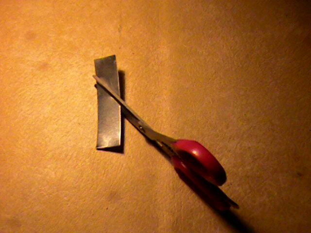
One major advantage to using flashing is the ease with which you can work it. It can be easlily cut with a good pair of utilty scissors. Do NOT use your XYL's favorite dress shears for this! |
When making your plates, lay out one of each, cut them out, and then use them as templates to layout the rest. Here are the plates, all cut out. Since no one is perfect, make sure you mark an index on each plate as you cut it out. This will insure proper alignment when you assemble the device. |
|
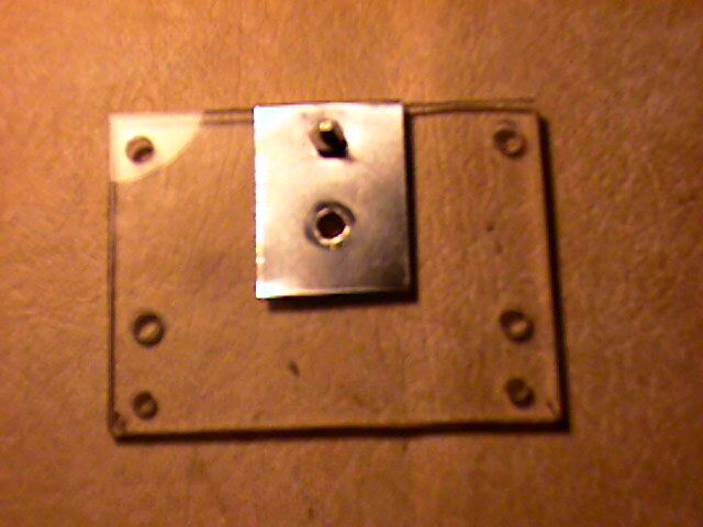
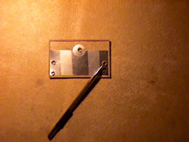
Drill the endplates. It is a good idea to drill both together so the holes will match front and back. To make the contact plate for the rotor, cut a strip of flashing long enough to cover the rotor shaft hole on both sides. After bending the strip over the endplate, drill a small hole to accommodate a 1" 6-32 brass screw. |
Next, drill the shaft holes in the rotor plates. Again, in order to insure the uniformity of the parts, you should drill all the holes at once. I used scrap Lexan to hold the plates in the jaws of a Vice-Grip. Dimple the top plate of the stack at the center of the hole. It is a good idea to drill a small pilot hole before drilling the 1/4" hole. |
|
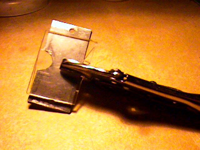
Now, take a rotor plate and a stator plate and tape them together in full mesh. Make sure the shaft tab on the rotor plate is properly aligned with the cut out in the stator plate. |
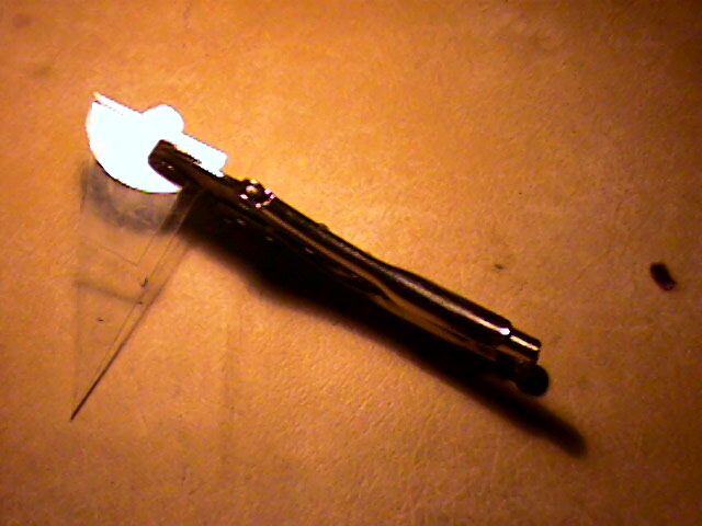
Align the shaft hole in the endplate with the shaft hole in the rotor plate and square the endplate over the parts to be marked. I used a carbide tip scribe for marking, but any sharp pointed object could be used. In a pinch, you could use the point on your pencil compass for marking. |
|
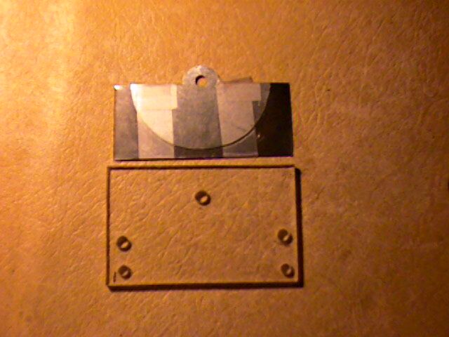
Separate the rotor and stator plates you just marked. Stack all of the stator plates together insuring that the rotor tab cutout matches and tape them. This will keep them from slipping when you clamp them for drilling. |
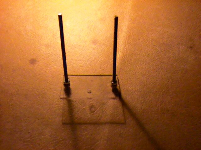
Cut the all-thread for the stator rails. For a 220pf capacitor of 12 plates, 4-1/2" is adequate. Mount these in the back end plate, leaving 3/8" to 1/2" beyond the outside nut. Secure them to the inside using 2 nuts per rail to leave adequate space for the rotor. |
|
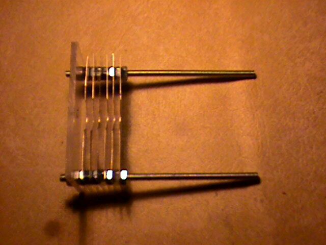
Begin mounting the stator plates. First flatten them as much as possible, removing the bows, twists, and curls. Make sure they are properly aligned. This is where the index marks you put on the plates come in handy. |
As you mount the plates, tighten the nuts finger tight - do NOT use a wrench. Excess torque will deform the plates, making alignment extremely difficult. Look for a bowing in the plate. Either the plate was not flat, or the nuts are too tight. Correct this now before proceeding to the next plate. |
|
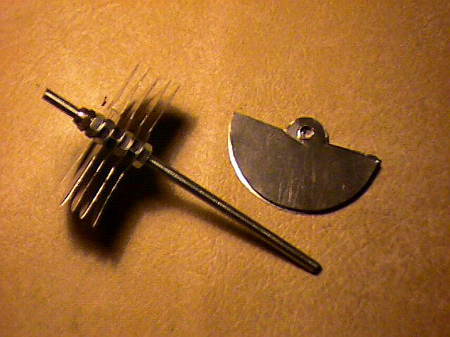
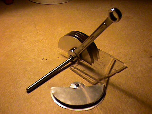
Once the stator is assembled, assemble the rotor, again flattening the plates as much as possible. The shaft should be cut an 1-1/2" to 2" longer than the stator rails. Use a stop nut as the last nut in the rotor assembly,and then a regular nut. |
This will hold the regular nut allowing you to torque the first plate into position, and will later be used to adjust the turn tension. Assembly of the rotor will require a wrench. As illustrated, use some kind of spacer to tighten the plates against. This will insure that the plates remain level and allow you to torque the nuts fairly tightly. |
|
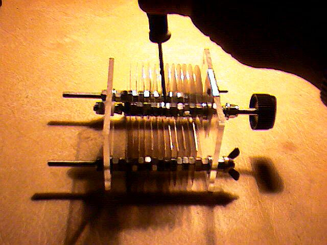
Now you are ready for final assembly. Hold the completed rotor in a full unmesh position and insert the shaft into the back endplate using 2 Teflon or Nylon washers on either side of the plate at the rotor shaft. You may need to add a washer to each side of the stator to allow space. Secure the rotor with a stop nut . Rotate the rotor to full mesh and install the front plate. Secure the plate with regular nuts on the stator. Place a flat washer, the compression spring, and another flat washer on the rotor shaft. Secure these with a stop nut. Tighten the stop nut till the spring compresses, tensioning the rotor shaft. Now tighten the stop nut on the other end of the rotor to center the rotor plates in the stator. Judge proper centering at the shaft. |
It is possible that you find the rotor turns too freely to suit you. You can adjust turns tension by tightening the inside stop nut on the rotor shaft against the backplate to provide a more pleasing tension. Likely, you will need to adjust the rotor plates. This is accomplished using a small screwdriver to slightly bend the plates at the shaft. Be gentle, a little at the shaft translates to a large movement at the outer radius. If you have developed a slight bow in a stator plate, use the screwdriver in the same manner at the nuts on the stator rail. Only as a last resort should you attempt to adjust the capacitor with needle nosed pliers. |
|
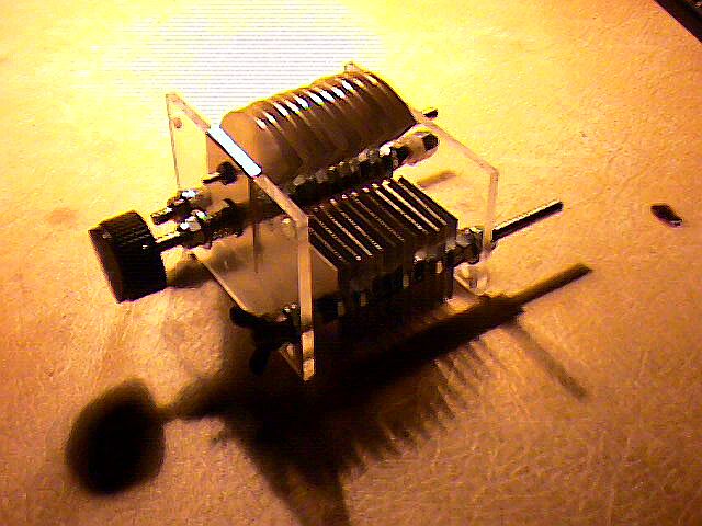
Now your capacitor is complete and ready for your project! Conclusion As I assmbled this unit, I came to the conclusion that Anwar's use of spacers, rather than nuts is probably a good idea. If I were using spacers, I would use a stop nut on either end of the assembly to prevent loosening. Flashing is not the best material to use. If you can find it easily, I would recommend a heavier gauge material. Anwar made a very valid point of which I was not aware when he critiqued my design, which I will pass on here. Sharp corners should be radiused to prevent arc over. It would be a simple matter to round of the corners with a mill file as you drill the holes. I suspect if I use significant power, I will probably have to rebuild the capacitor with radiused corners after it arcs over. Transmitting air variables are becoming scarce and expensive, even at Hamfests, and the kit capacitor from TenTec is over $50.00. This is a viable alternative for medium power projects. Though I have not tested it, I suspect a carefully aligned capacitor of this type would easily carry a kilowatt. This would be perfect for a Transmatch or the coupling capacitor in a Loop Antenna without breaking the bank. Ham Radio is a fun hobby, but it doesn't necessarilly have to be expensive, as long as you carry on the HomeBrew tradition! I would like to thank Anwar von Sroka, whose excellent article inspired this project. A small little program to calculate capacitor parameters (along with many other GREAT design programs) can be found at http://www.qsl.net/ve3sqb/ Make sure you look at my Transmatch Project in which I used a homebrewed double ganged capacitor. |
Copyright 2003 David Hammack, A.R.S. N4DFP