Background to this project.
This
little project arose from a desire to experiment with some of the more
"traditional" methods of radio construction which enjoyed
popularity some 70 years ago. I wanted to find out for myself what kind
of performance could be achieved using simple circuits incorporating
Valves/Vacuum Tubes and low budget design techniques popular in the
1930's. In particular I was curious to try out "Spider" coils and a
Regenerative Detector using a low-mu (low gain) triode as the active
device.
There
is a great deal of "folklore" surrounding regenerative receivers
with claims of exceptionally good performance from these simple
designs. For the most part these claims are well justified. Its true to
say that a well constructed regen receiver of good design will give
pleasing performance. Over the years a number of regen receivers
have been constructed here at M0AYF for both broadcast and ham radio
reception using vacuum tubes and/or solid state devices.
I can confirm that they do indeed perform as advertised. But
most of the
receivers built here had taken advantage of using modern
components and construction techniques so it was interesting to build
the "retro" receiver using more traditional construction techniques and
then to compare the performance to that of newer designs.
In order to remain as faithful as possible to the traditional methods
of construction and technology available in the 1930's it was decided
that low-mu (low gain) triodes would be used for the various stages of
the receiver. Though I have a small quantity of 1930's triode
valves/tubes in the M0AYF junk-box the decision was made to save these
for a future "retro" project. So a suitable active device to serve
as a replacement for the low-mu triodes had to be found. Physical
inspection of the internal construction of a VFD (Vacuum Fluorescent
Device) revealed that it possessed all of the key electrodes found in a
triode valve/tube.
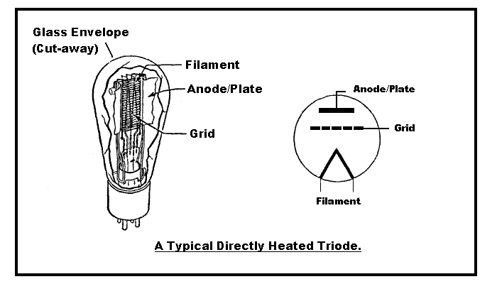
Valves/Vacuum Tubes and "Triodes in Disguise"
A basic triode valve/tube consists of three electrodes, a heated
cathode, a control grid and an anode/plate. The cathode electrode
in a typical directly heated triode takes the form of a specially
coated filament. This coated filament is arranged such that when an electric
current is passed through it the filament will heat up and "glow"
causing electrons to be freely emitted. This is generally termed a
"directly heated" or "self heated" cathode. Below is a cut-away diagram of a triode
valve/tube which is of the directly heated type and typical of
those used in the 1930's for domestic broadcast receivers.
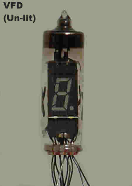
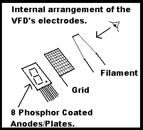
A Vacuum Fluorescent Device (VFD) is a display device used extensively
in domestic electrical goods such as VCR's, bedside clocks and
microwave ovens to name but a few. Though it may not be immediately
obvious the internal construction of a VFD is very similar to that of a
simple directly heated triode valve/tube, a sort of "Triode in Disguise". The main difference is that
the VFD is of a planar construction which is in contrast to the
coaxial construction of the typical valve/tube shown in the diagram above. The
VFD's used in this project contain a single 7-segment display within a
glass envelope and physically resemble a small valve/vacuum tube. The
VFD has a directly heated cathode (filament wires), a control grid and
at least one anode/plate coated with a phosphor which emits light when
struck by electrons. Most VFD's have more than one phosphor coated
anode/plate each with its own electrical connection to provide a multi
segmented display. For example a "numbers" display would typically have
at least seven phosphor coated anodes/plates and possibly a few more to
indicate the sign and decimal place.
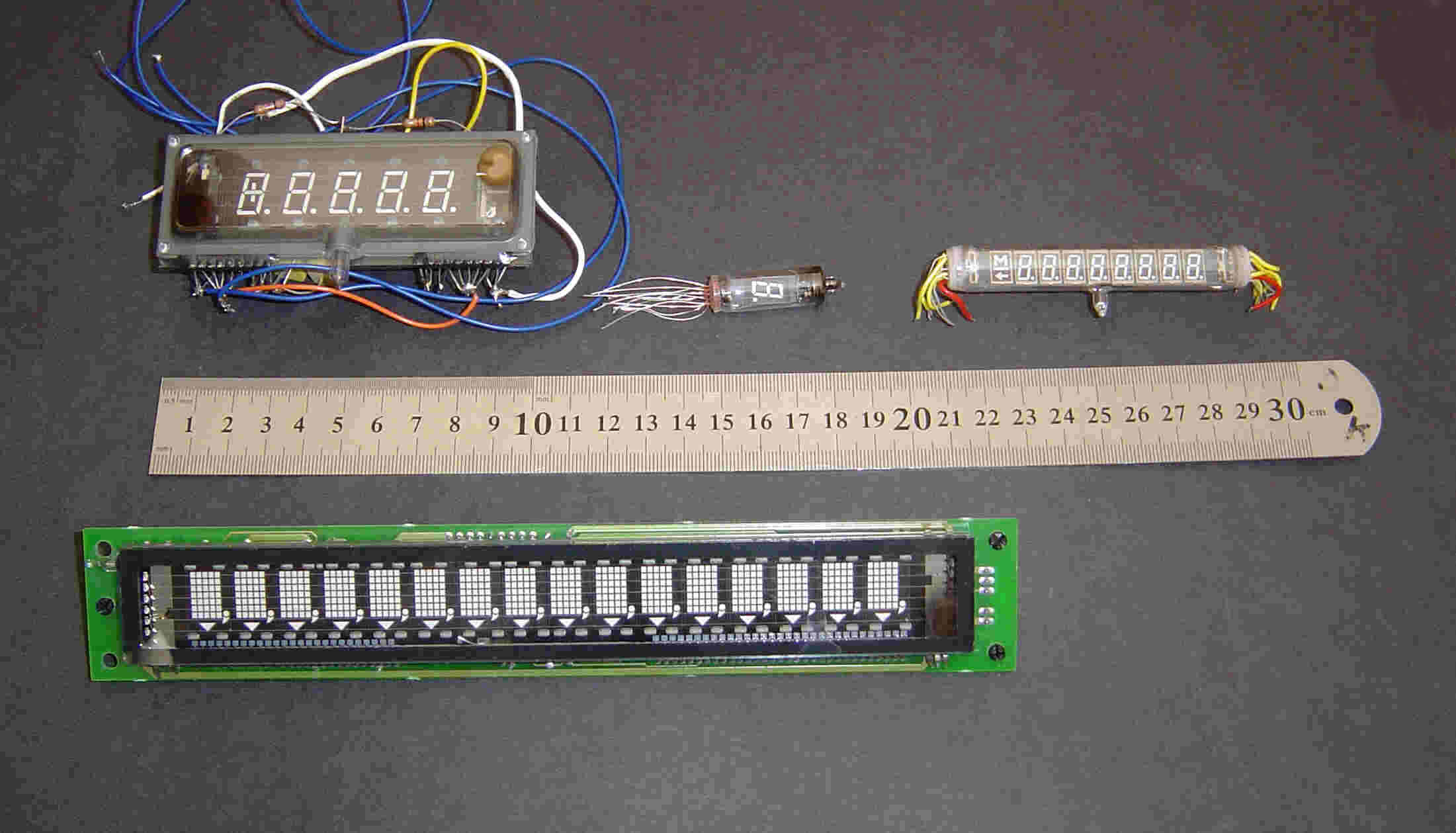
Two
example images of the VFD's used in the retro receiver are shown below. Click on the
thumbnails to see a larger image.
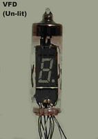
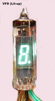
 In the image (above right) of the VFD tube "lit-up" both the grid mesh and the two filament wires are clearly visible.
The internal
electrodes of the the VFD device are shown in the diagram on the right.
The phosphor coated anodes/plates have separate connections so that
individual segments can be switched on or off to produce different
numbers.
In the image (above right) of the VFD tube "lit-up" both the grid mesh and the two filament wires are clearly visible.
The internal
electrodes of the the VFD device are shown in the diagram on the right.
The phosphor coated anodes/plates have separate connections so that
individual segments can be switched on or off to produce different
numbers.
In the example VFD shown above the filament supply Voltage is around
1.5 to 2 Volts and when used as a number display the anode/plate
Voltage is about +40 Volts. In multi-VFD's (those able to display more
than one digit at a time) the filament Voltage is generally higher at 4
to 6 Volts though the anode/plate Voltages are still of the order of
+40 Volts or so. The component parts of the seven segment VFD display
shown above are enclosed in a transparent glass envelope from which all
the gas has been removed. i.e. A "hard" vacuum just like that of the
triode valve example mentioned earlier.
All the VFD displays I have encountered have only one set of
filaments for the whole display regardless of the number of digits or
characters it may have. In normal display applications the filament
will be run from an AC supply. However, for use in radio work it is
necessary to use a DC supply for the filaments. This is because an AC
supply would cause an unwanted signal to be introduced into the
circuit. Using a DC supply for the filaments does not pose a major
problem when using single digit/character displays but with multi-digit
displays within a single glass envelope (such as those found in a VCR)
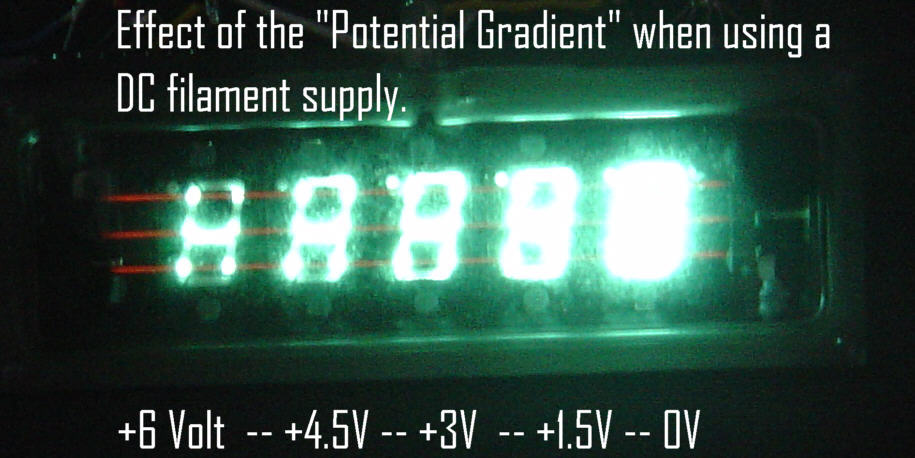
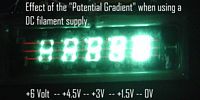
the effect of the DC filament supply is to produce a "potential
gradient" across the display. The effect of this potential
gradient is to cause the brilliance of the display to be uneven across
the total display area. The reason this happens is because the current
passing through the filament wires causes a progressive Voltage drop
along the filament wires which acts as a progressively increasing bias
to the individual sections of the display.
For example, in a VFD
display with say five separate sections enclosed in a single glass
envelope side-by-side (such as a clock display for a VCR) you would
expect to see a significant difference in brightness from one one end
of the display to the other due to the potential gradient effect. If the filament supply was say +6 Volts
then the section of the display nearest the 0 Volt end of the filament
wires would be the brightest while the section at the +6 Volt end of
the filament wires would be darker. Its the same as putting an
increasing positive bias on the cathode of a valve/vacuum tube, the
greater the positive bias on the cathode the more the current in the
valve/tube reduces. A picture of a five section VFD display using a DC
filament supply showing the effect of potential gradient can be seen
below. Click on the thumbnail for a larger image. See also reference 5 in the "References and Links" section at the bottom of this page.
Here are some more examples of VFD display devices salvaged from
various electronic units which had been scrapped. Click on the
thumbnail below for a larger image.

One
of the reasons that VFD's have enjoyed widespread use for so long is
that they produce a bright display with a wide viewing angle. The spectrum
from the display is also fairly wide for any given colour giving a
softer light which is pleasing to the eye. In recent years the VFD has
been increasingly replaced by L.E.D. and/or L.C.D. displays which continue to develop
and offer higher efficiency, longer life and are physically more rugged
than the VFD.
For more information on V.F.D.'s see references 1 and 2 in the "References and Links" section at the bottom of this page.
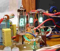
VFD's used as Valves/Vacuum Tubes.
The receiver described here follows mostly tried and trusted methods of
construction with one major exception, VFD's have been used in place of
valves/vacuum tubes in order to simulate low-mu triodes and to satisfy
my own curiosity regarding the use of VFD's for non display
applications.
Single VFD tubes (sometimes described as "first generation" VFD's) salvaged from an old desk-top calculator have been
used because they seemed well suited for constructing the individual
stages of the receiver on a one tube/VFD per stage basis. In each case
all the anodes/plates (seven segments plus decimal point) of the
tubes/VFD's have been strapped together to form a single anode/plate
connection. In tests this arrangement seemed to give the best
performance. Though there is some evidence of the potential gradient
effect mentioned earlier it caused no problems in practice aside from a
very slight non uniformity of brilliance over the display area. Indeed,
if you look at this "VFD Lit-Up"
image it is hard to see any significant difference in brightness
between the top and bottom of the display. Using single tubes/VFD's
also permits physical separation of the individual stages of the
receiver which makes it easier to achieve good stability.
First tests using VFD's in place of triode valves/tubes did not look
very promising. In normal display operation a VFD may have only +40
Volts on its anodes/plates and in order to secure sufficient current
flow and display brightness they often resort to some positive Voltage
bias applied to the control grid which in turn permits some control
grid current to flow. This mode of operation is quite satisfactory for
display purposes but is not well suited for small signal amplification.
For the initial tests I used a +40 Volt DC supply for the anodes/plates
since this is the Voltage which had been used in the desk-top calculator
from which the VFD's had been salvaged. I joined all the anodes/plates
together to form a single anode/plate connection. A resistor in the
anode was chosen to limit the current to a safe value of around 100
micro amps for testing. This was about the same value of current used
for each individual segment of the display when used in the calculator
and provided a bright display.
With +40 Volts on the anodes I could not get the VFD's to work
correctly as a small signal amplifier. Indeed, with the control grid
connected to zero Volts via a one mega-Ohm resistor little or no
current would flow from the filament to the anodes/plates. Increasing
the anode/plate Voltage to +120 Volts improved matters and I could now see some
signs of current flow (glowing anodes/plates) and signs of
amplification. Finally I increased the HT supply to +200 Volts (and
also increased the value of the anode load resistor) at which point the
VFD device began behaving much like a valve/vacuum tube. For information about other experiments with VFD,s see my "VFD" page.
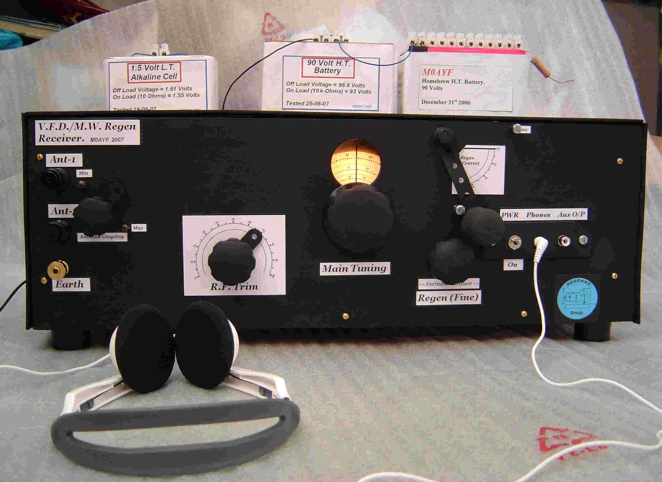
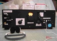
Receiver Description.
The
receiver is a "regenerative" type or (if you prefer) "straight"
set
with some controlled positive feedback applied to enhance the
selectivity
and sensitivity. This type of receiver was very popular in the 1930's
and still finds favour today among radio enthusiasts. If you would like
to know more about this type of receiver then just do a Google search
for "regenerative detector" and you will find plenty of references. In
addition to Google you may be interested in a very active and well
behaved Yahoo group called "regenrx", for more information on this
group see reference 13 in the "References and Links" section at the bottom of this page. Alternatively, have a look at my "Regen" page.
Since the VFD's
are in a triode format it means that all the stages of the receiver
would have to use circuitry best suited to the triode configuration.
Though the gain of the individual tubes is quite low they are
electrically very "quiet" resulting in a good signal-to-noise ratio. This is also true of "real" triode valves/tubes.
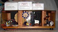
The configuration chosen for the receiver is a 1-V-2 arrangement, that
is, one stage of RF amplification followed by a regenerative detector
stage and two stages of audio frequency amplification. The set-up is as
follows...
R.F. stage = single neutralized triode/VFD.
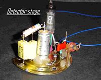
Detector stage = single triode/VFD.
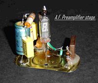
First A.F. (preamplifier) stage = single triode/VFD.
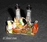
Second A.F. stage = two triodes/VFD's wired in parallel.
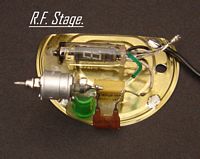
The R.F. stage.
The use of an R.F. stage in a regenerative receiver is often
misunderstood. When correctly implemented the regenerative detector is
exceptionally sensitive and has no need of additional R.F.
amplification below frequencies in the upper H.F. range. However, an
R.F. stage is often added in front of a regenerative detector stage
even at L.F./M.F. This is nothing to do with "boosting" the R.F. signal
but more to do with isolating or decoupling the antenna from the
detector stage. A number of problems can arise when the antenna is
tightly coupled to the detectors tuned circuit, these problems include,
detector radiation, "dead spots" within the tuning range, overloading
of the detector and mis-tuning of the detector tuned circuit by the
antenna. The cure for all these effects is the addition of a low
or unity gain R.F. stage. This can be of the tuned or un-tuned variety
but I chose to use a tuned R.F. stage because the extra tuned circuit
serves to improve selectivity and provides increased performance when
tuning in weak signals which are very close in frequency to stronger
(local) radio signals.
In rough tests on the bench it was found that a VFD R.F.
stage would operate at medium wave frequencies without any
neutralization and remained stable. This is perhaps due to the
low-mu/low gain of the VFD's. However, for "peace of mind" it was
decided that a neutralized triode circuit would be used loosely based
on the "Hazeltine-
Neutrodyne" designs
which date back to the 1920's. Neutralization is often required in
order to counteract the effects of grid to anode/plate capacitance
which exists in all valves/tubes to some extent. This grid to
anode/plate capacitance can result in some of the amplified anode/plate
signal being returned to the control grid. Depending on the
amplitude/phase relationship of the feedback it can result in
instability or oscillation of the stage. The schematic of the RF and
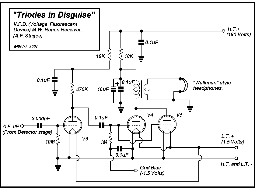
Detector stages of the receiver appear below.
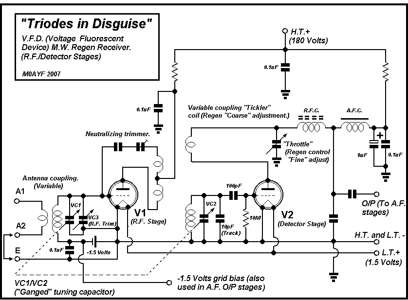
The neutralization circuit works by feeding back a signal of the same
amplitude but 180 degrees out-of-phase with that of the signal due to
grid/plate capacitance. The amplitude of the out-of-phase signal is
adjusted using the "neutralizing trimmer" shown in the schematic above.
When correctly set the unwanted feedback caused by the anode/plate
capacitance is canceled out by the out-of-phase feedback signal at
which point the stage is said to be "neutralized". I chose this
particular method of neutralization because it proved to be easy to
implement and set-up.
The R.F. stage also has a negative bias Voltage of 1.5 Volts applied to
the control grid. In tests the stage worked perfectly well with or
without the bias but with the negative bias applied the VFD's
standing current was reduced which in turn reduced the battery
consumption. I also felt that a little bit of negative bias would
ensure better linearity of the R.F. stage in the presence of strong
signals.
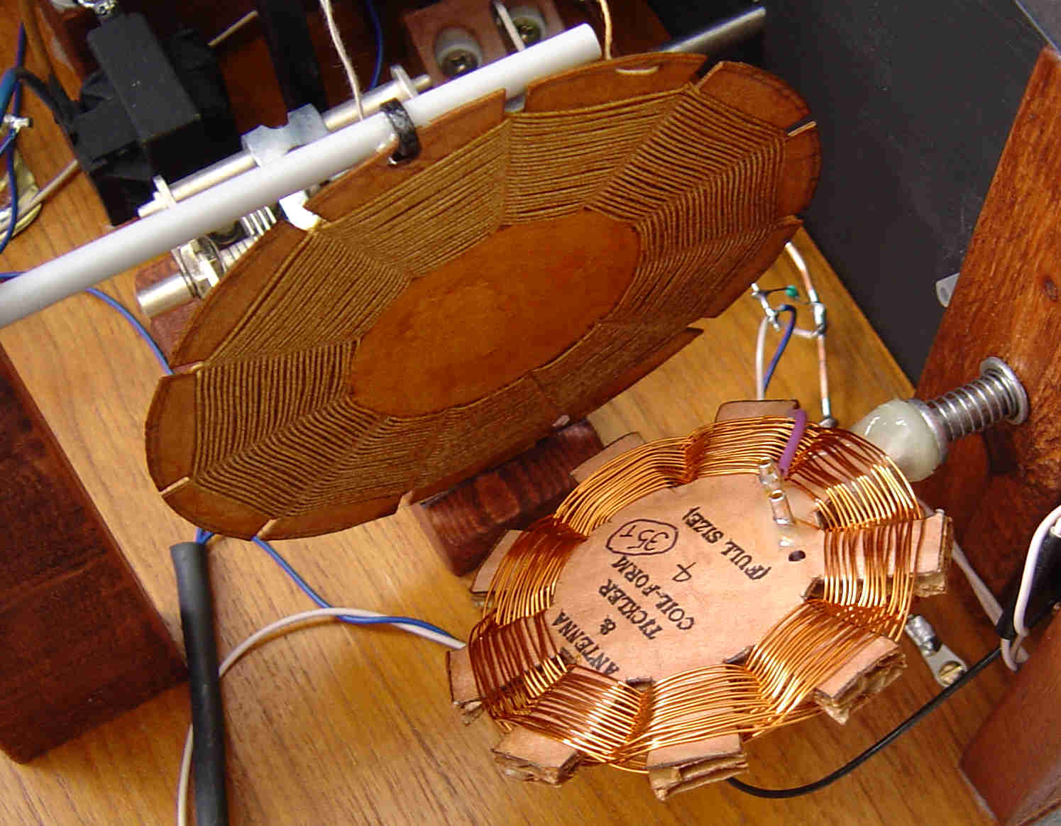
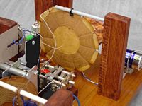
Here at M0AYF we have a very strong local signal at the higher end of
the MW band from a transmitter located just 17 miles away so in order
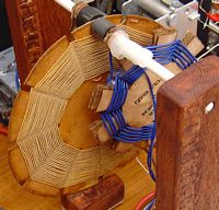
to avoid overloading of the R.F. stage a variable inductive couping was
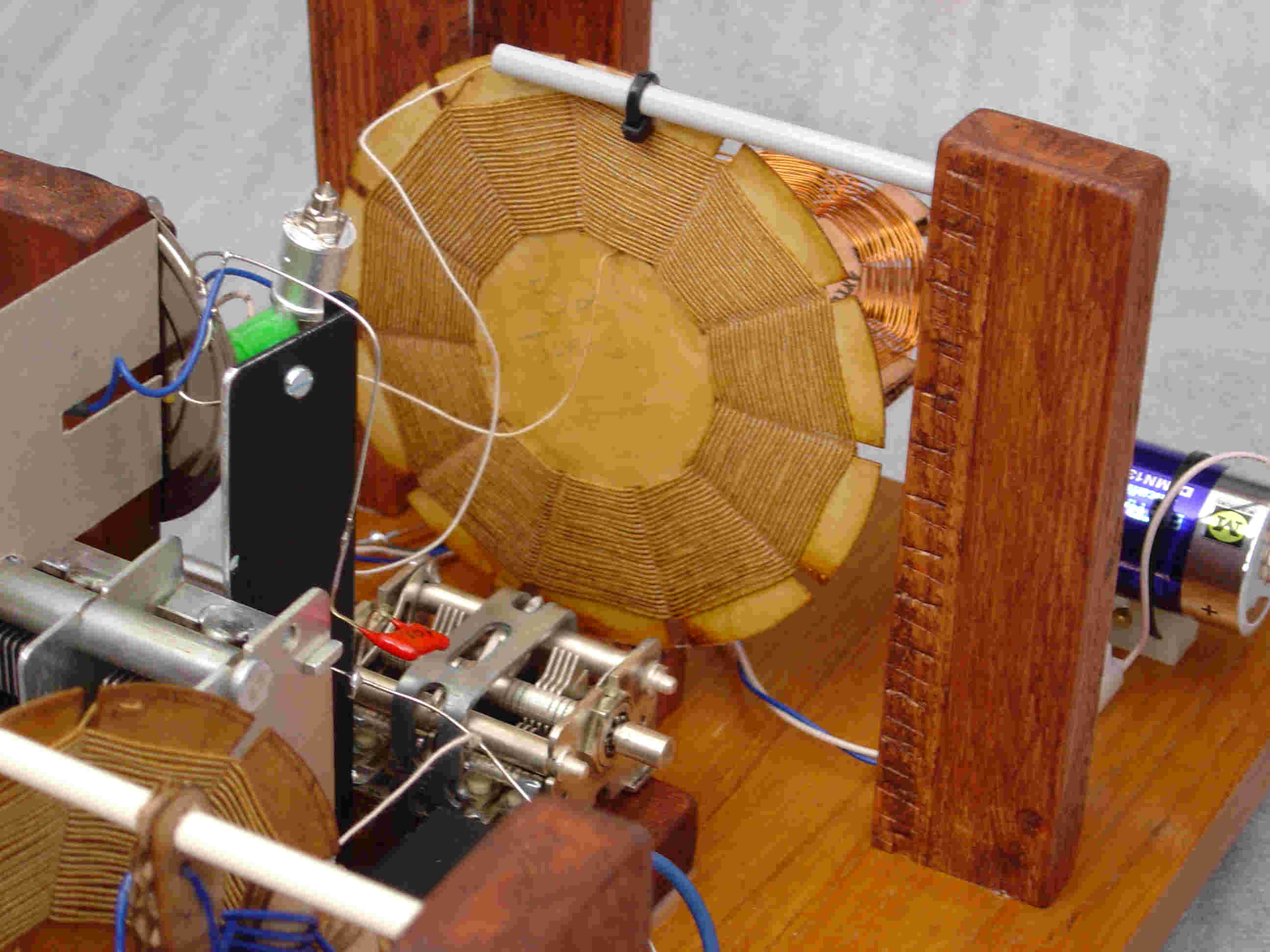
implemented. The fixed spider coil which forms part of the tuned
circuit in the R.F. stage is coupled to a smaller rotating spider coil.
This second smaller coil is able to rotate through 90 degrees and is
adjusted via a front panel control. When the two coils are at right
angles to each other the coupling is at a minimum. A picture of the
coupler is shown below. Click on the thumbnail for a larger image.

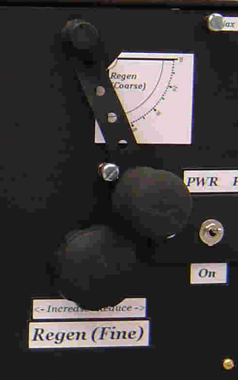
Regen Detector Stage.
The
regenerative detector stage is fairly conventional and is of the "grid
leak detector" variety incorporating positive feedback from the
anode/plate via inductive coupling using a "tickler" coil. Because the
receiver tunes over the entire MW band (plus a little extra) it was
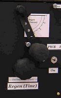
decided that both a "coarse" and "fine" regen (feedback) control would
be fitted. When tuning over a wide range of frequencies using a regen
circuit it is often found that the regen (positive feedback) tends to
fall-off or reduce as the frequency gets lower. While it is possible to
make a regen control with sufficient "scope" to work correctly over the
full band it is often found that the control becomes very "coarse" in
operation making the receiver difficult to use. Smoother control of the
regen results if the operation of the control is s-p-r-e-a-d out. This
can be done using two controls for regen, one coarse and one fine.
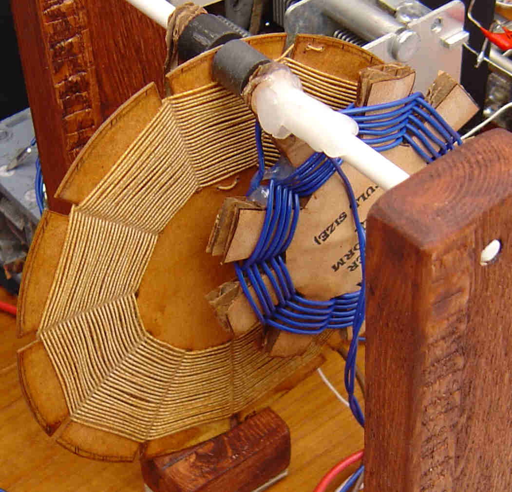
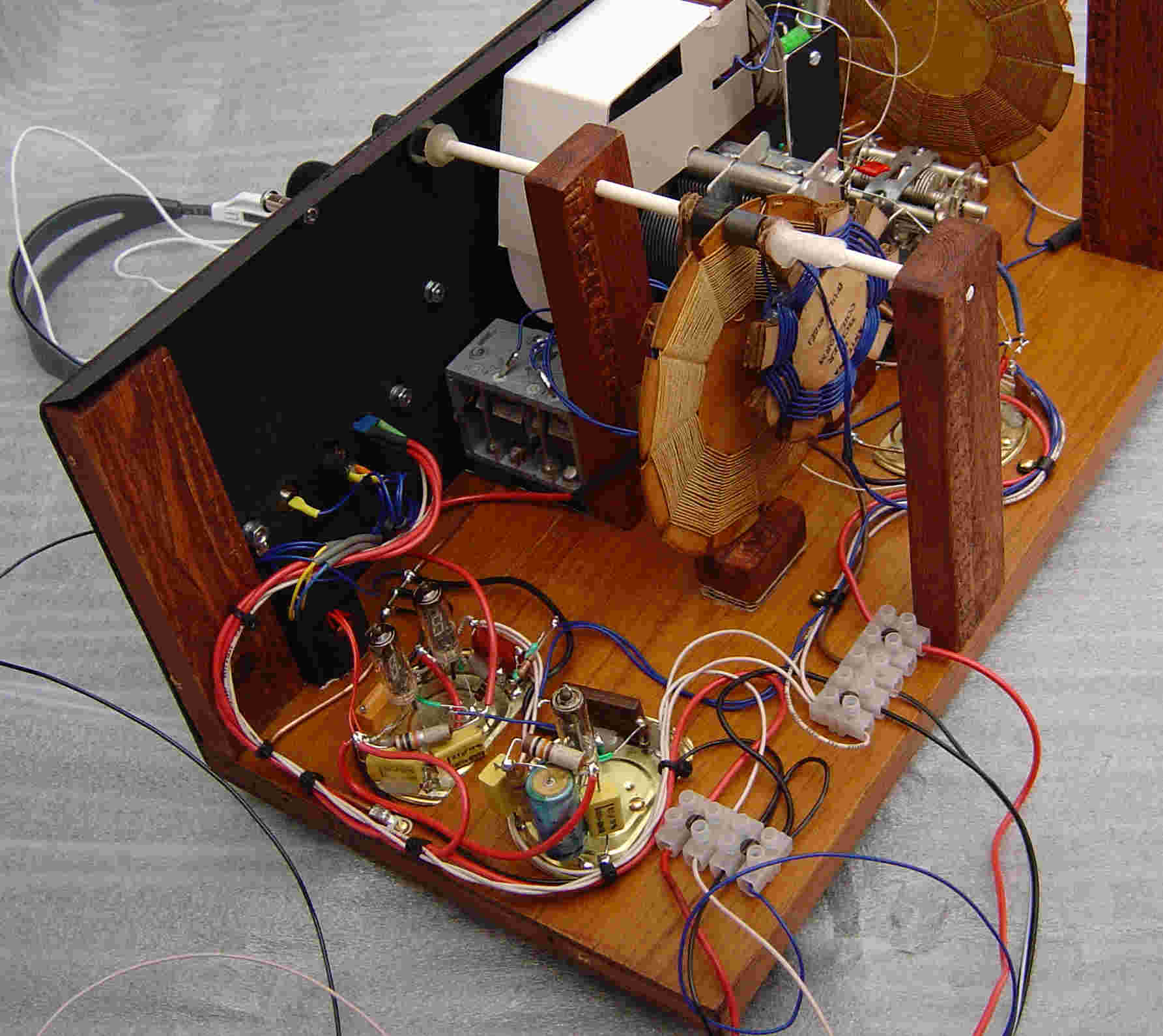
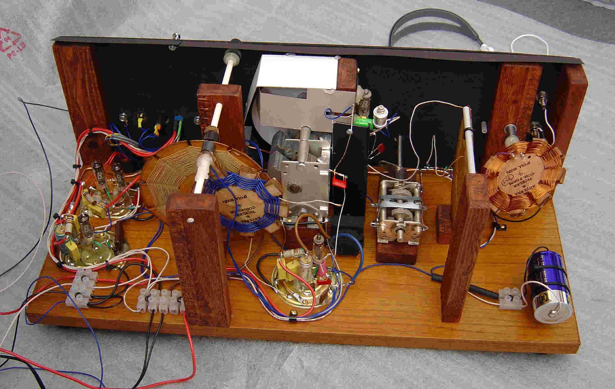
The coarse regen is implemented using another variable inductance
coupling, unlike the R.F. stage antenna coupler the coarse regen
coupler has both the detector stage tuned coil and the feedback
(tickler) coil in-line with each other. Control of the tickler coupling
is achieved using a rotating axle (plastic knitting needle) upon which
the tickler coil is mounted. The axle has 90 degrees of rotation and is
coupled to a front panel control. The rotating axle also passes through
the detector coil but since the detector coil is not fixed to the axle
it does not move. Fine control of the regen is implemented using a
variable capacitor connected from one end of the tickler coil to ground
as a "throttle" control arrangement. Some pictures of the mechanical
arrangements can be seen below. Click on one of the thumbnails for a
larger image.
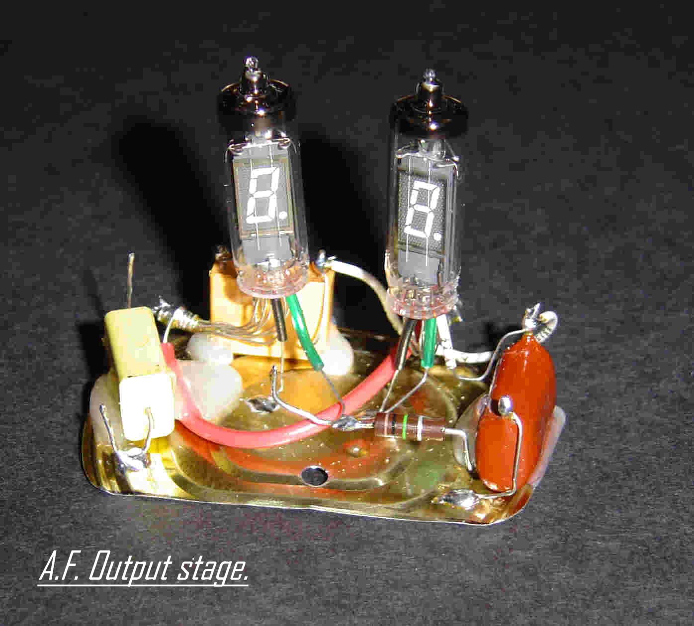
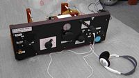
AF Stages.
The A.F. stages of the receiver need little explanation except to say
that three tubes have been used in order to give "rock
crushing" volume with reasonably low distortion into a pair of low
impedance personal stereo headphones. The use of two tubes in parallel
for the headphone output stage was to give added "peace of mind" as it
was thought that a single tube might be "stressed" a little.
Theoretically the two tubes (when connected in parallel) should be
closely matched but in practice I selected two tubes at random and
found the current spit between the two tubes was pretty evenly
distributed. The same 1.5 Volt negative bias supply used for the R.F.
stage is also used for the output stage in order to move the operating
point of the VFD's to secure a more linear (lower distortion) region
and thus reduce distortion on loud signals. A schematic of the A.F.
stages appears here.
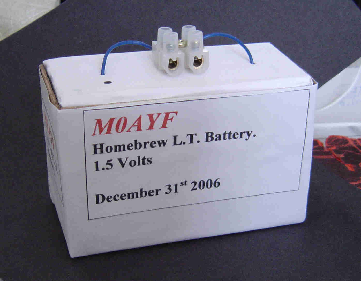
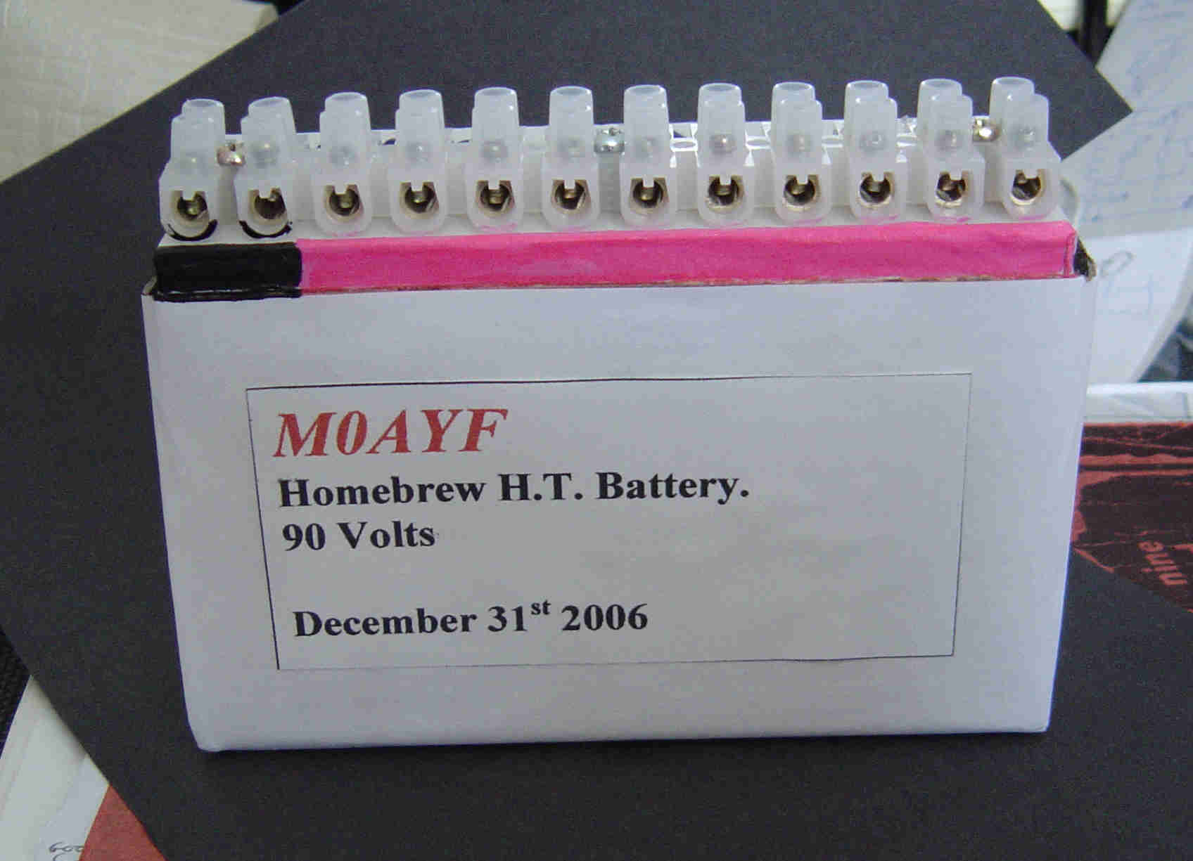
Power Supply.
The
receiver requires three separate power supplies, a 1.5 Volt filament
supply at around 300 mA, a 1.5 Volt negative grid bias bias supply and a H.T. supply of
between 150 and 200 Volts at around 1 mA. All three supplies are derived from dry
batteries. Though less convenient than a mains powered unit they offer
the advantage of a truly "silent" background when tuning between
stations, no "hum" or "buzz" from power supply transformer magnetic fields or power
supply harmonics etc.
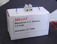
Both the negative grid bias supply and the filament supply use a
1.5 Volt alkaline cell. Alkaline cells have a very long shelf life
which makes them ideal for the grid bias supply. The grid bias supply
draws virtually zero current regardless of the radio being switched on
or off so the cell will last for perhaps years. I used a "run down"
cell for the negative bias supply since the internal resistance of the
cell makes little difference in this application and because it helps to recycle an old cell.
An alkaline cell is also used for the filament supply, all five VFD
tubes have the filaments connected together in parallel so a single
cell runs all five tubes. Wires have been soldered to the terminals of
the cell such that it could be mounted in a cardboard box with external
screw terminals fitted. This is a re-usable box which permits a new
cell to be fitted when the old one is exhausted.
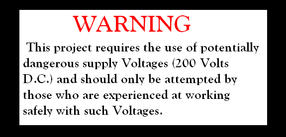
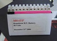
The
H.T. supply (up to 200 Volts) is derived from a total of twenty 9 Volt
transistor radio batteries. Two H.T. battery boxes house the batteries
(ten in each box) and are connected in series to give a nominal +180
Volts. In practice the Voltage is
greater than +200 Volts when the batteries are new. This is
potentially dangerous so please exercise caution if you choose to
replicate any of the experiments outlined on this page. Because
of the relatively low consumption of the receiver (about one milliamp) and only intermittent
use the batteries will last for a very long time. A couple of pictures of
the battery boxes appear below. Just click on the thumbnails for a
larger image.
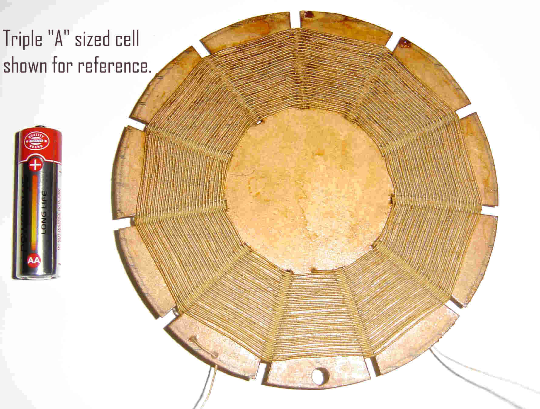
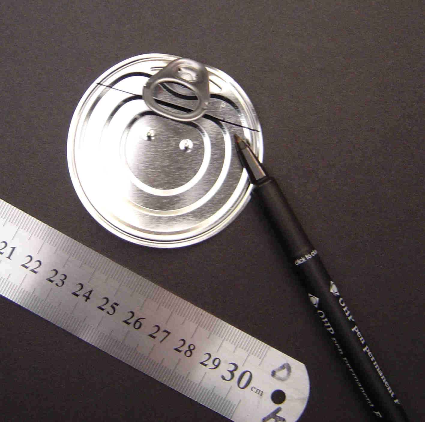
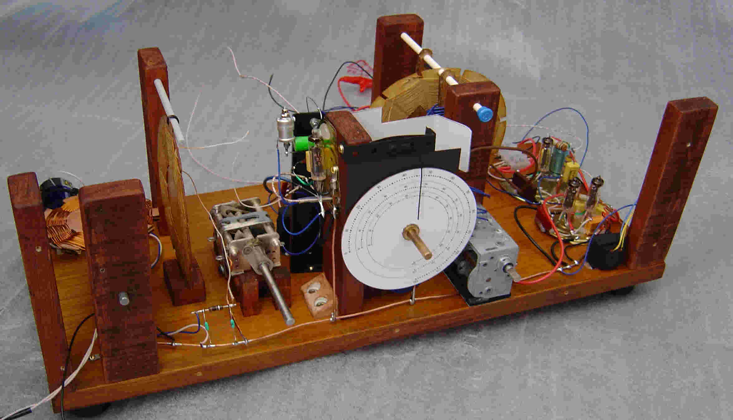
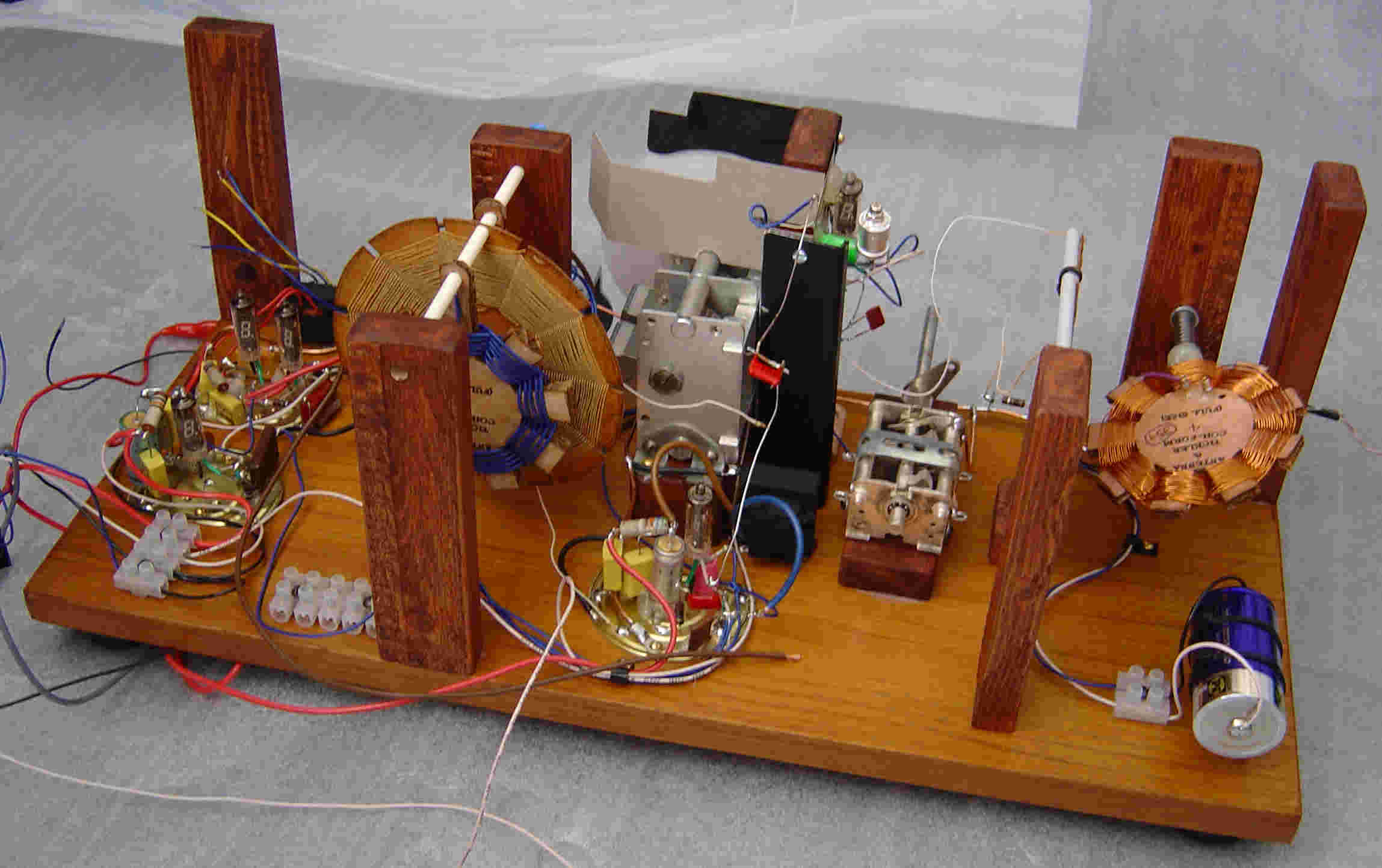
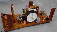
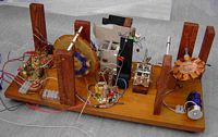
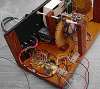
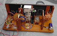
Receiver Construction and Pictures.
The construction techniques used are intended to reflect some of the
methods used for home constructed receivers back in the 1930's.
These are generally low budget methods with many of the components home
made if
possible. I stopped short of making my own resistors and capacitors,
while this is possible it would have also taken much longer to build
the receiver. I was also very impatient to see how the VFD's and
"spider"
coils performed in the finished radio. Some more information and
templates for making spider coils can be found in references 9, 10, 11
and 12 in the "References and Links" section at the bottom of this page. A close-up picture of one of the
spider coils appears below. Just click on the thumbnail for a full
sized image.
The
materials used include a varnished wood baseboard to serve as a chassis
and an enclosure made from scrap hardboard which was painted mat black.
The individual stages of the receiver are constructed on tin lids
salvaged from food cans. They made effective supports for the
wire-ended VFD devices and also provided a local "ground plane" area.
Interconnection between the different stages is via insulated wires.
More information on the use of food cans for ham radio applications can be found on Hans Summers (G0UPL) excellent web site. The "tin lid" construction can be seen in the images below. Just
click on one of the thumbnails for a larger image.
Test Results.
The "Retro-Regen" was tested using a home-brew Wide Bandwidth Active Loop Receiving Antenna and
performed much better than expected. It easily matches or (in some
cases) exceeds the performance of an old Cossor model 393 regen
receiver which was manufactured in the late 1930's and used here as
a reference with which to compare the retro regen's performance.
While the retro regen is not capable of driving a loudspeaker directly
it more than makes up for this in other respects. The receiver is free
of "reaction chasing" (or regen chasing), this is an annoying problem
which sometimes plagues regen receivers. The symptoms of reaction/regen
chasing are a difficulty in securing the optimum tuning point as the
regen control is advanced (more positive feedback) such that as the
operator advances the regen the main tuning also has to be re-adjusted.
This in turn causes the optimum regen point to shift so it to must be
re-adjusted. This interaction or "chasing" between the two controls
continues and gets worse as the regen is advanced. The cause of
reaction chasing is often due to over coupling of the "tickler" coil to
the detectors tuned circuit such that changing reactance in the
feedback circuit is coupled to the detector tuned circuit and "pulls"
the tuning a little. Thankfully, the retro regen behaves well with no
evidence of reaction pulling. Some MP3 clips of the retro-regen in action can be found in the "MP3 Audio Clips" section of this web page.
The receivers sensitivity is very good and weaker stations can be
pulled from the forest of stronger EU stations quite easily. There is
some loss of sensitivity at the L.F. end of the MW band due I suspect
to the reduced coupling between the R.F. and Detector stages as the frequency gets lower. Within
the limitations of the regenerative detector the receiver copes fairly
well with strong signals, in the event of a strong local signal
s-p-r-e-a-d-i-n-g over the band the antenna coupling can be reduced
which usually cures the problem. One unexpected result of the receivers
high sensitivity is its ability to receive signals with no antenna
connected, at first this was thought to be due to pick-up in the wiring
but further tests revealed that the home made spider coils behaved as
small frame antennas. Had the receiver been housed in a steel box this
would not happen.
Though the gain of the individual tubes is quite low they are
electrically very "quiet" resulting in a good signal-to-noise ratio. This is also true of "real" triode valves to.
In common with regular battery valves (1T4 and
similar) the VFD's are "microphonic" to some extent so if they are
tapped with a
pencil while powered-up a "ping" can be heard in the headphones.
Thankfully the wire ended connections of the VFD's act as shock
absorbers to some extent and reduce the effects of vibration from the
case and its surroundings. This microphonic effect is mainly due to the
filament and internal electrode structure of the VFD mechanically
vibrating. The effect becomes more problematic with an increasing
number of cascaded audio stages. The Retro-Regen has three cascaded
audio stages, the detector (which also amplifies at A.F.) followed by
an A.F. pre-amplifier stage and finally the A.F. headphone output
stage. Since the detector is the first of these cascaded A.F. stages it
is also the most microphonic. You can hear the "ping" sound made by the
detector stage VFD tube being "tapped" by downloading and playing
the MP3 audio clip (number 8) in the "MP3 Audio Clips"
section of this web page. Another VFD experimenter has made full use of
this microphonic effect in VFD tubes by building a pseudo ring
modulator, see reference 6 in the "References and Links" section at the bottom of this page.
One amusing side-effect of using VFD's for the receiver is the "visual
feedback" they provide. When the VFD's are in the "linear region" or
driven with very small signals then the "glow" is continuous. However,
if the VFD's are over-driven into the non linear region then they can
be seen to "flicker", this effect is most noticeable on the A.F. output
stage VFD's on strong/loud signals. Similar visual feedback occurs with
the detector stage, as the detector is tuned through a strong signal
the brilliance of the glow can be seen to reduce slightly. This is
caused by the grid-leak detector action, as the negative Voltage builds
up on the control grid due to the strong signal it biases the VFD tube
so as to reduce the quiescent current. As the signal strength gets
higher so to does the negative bias and hence a greater reduction in
brilliance of the VFD. This reduction in brilliance of the VFD detector
tube can also be seen as the detector is taken into oscillation.

5)
With the regen advanced to a point just below oscillation the B.W. is
very narrow making the tuning very sharp. This gives a characteristic
"swoosh" sound as the station is tuned in.
6) Another example of tuning the receiver with the regen control advanced to a point just below oscillation.
7) A demonstration of a broadcast station being "faded out" using the antenna coupler as an R.F. attenuator.
8)
This is the "PING" sound heard in the headphones when the detector tube
is lightly "tapped" with a pencil due to microphonic effects caused by
the internal electrode structure of the tube vibrating.
Final Comments.
This
receiver turned out to be a very rewarding and educational project, I
discovered several new things about regen circuits and VFD's which
have inspired several new projects. These include a VFD transmitter, a
VFD 40 Mtr amateur band crystal controlled converter and
several other VFD regen designs. These additional projects are (at
the time
of writing) still undergoing tests on the work bench but may (in time)
find themselves on a web page. Of those projects listed above the
frequency converter has given very encouraging results. When
connected in front of the retro-regen it permits reception of the 40
Mtr amateur band. Reception of AM/CW and SSB are all possible. MP3
audio clips 1 and 2 in the "MP3 Audio Clips" section of this web page demonstrate SSB reception achieved using the 40 Mtr VFD converter ahead of the retro-regen.
For anyone considering building a project using VFD's salvaged from
VCR's or calculators etc then please make sure that the VFD's are fully
operational before you start. Old VCR displays in particular are
sometimes lacking in brilliance. This lack of brilliance may be the
result of long hours of service resulting in damaged or burnt phosphors
or the result of failing emission from the cathode/filament. If the
lack of brilliance is due to worn phosphors then the emission may still
be good enough for VFD radio experiments but if the loss of brilliance
is due to failing emission then this may pose a problem for prospective
VFD radio use. So, look for a surplus or scrap item which still has a
working VFD with a bright display.
For information about other experiments with VFD,s see my "VFD" page.
A number of other radio hams and experimenters have also used VFD's in
other applications, see references 3, 4, 5, 6 and 7 in the "References and Links" section at the bottom of this page.
Finally, if after reading this you decide to build any projects using
VFD's or if you have already built a radio project using VFD's then
please drop me a line, I would be interested to hear about your
experiments.
Reference 1) Some general information about VFD's.
Reference 2) More in-depth information about the VFD's internal construction and operation.
Reference 3) A VFD Headphone Amplifier from Dietrich Drahtlos.
Reference 4) AC7ZL's Excellent and detailed page also dedicated to alternative uses for VFD's.
Reference 5) YouTube
video of AC7ZL's Crystal Set Plus VFD Audio Amplifier, this video also
shows the effect to the "Potential Gradient" on the intensity of the
VFD display when a D.C. filament supply is used.
Reference 6) A Pseudo Ring-Modulator using a VFD. This project demonstrates the "microphonic" effects of VFD's.
Reference 7) YouTube video of a single tube VFD clock which uses a similar VFD to those used in the regen receiver on this page.
Reference 8) You
must see David Schmarder's home page, here you will find links to some
of his home-made "Retro-Style" radios which really set a high standard.
Reference 9) David Schmarder's very detailed page on "Spider Coils".
Reference 10) Here
is a link to a template in PDF format for making spider coils. This is
the same template used to make some of the coils in the receiver
detailed on this page.
Reference 11) How to make a re-usable "Spider" coil former from an old CD/DVD.
Reference 12) Another template in PDF format for marking out an old CD/DVD for use as a "Spider" coil former.