Custom Meter Faces
A Pictorial Instruction
I recently had the need for a number of analog
meters to complete a project in progress. I quickly found that
these meters can be expensive! However, I also found there are
reasonably priced surplus meters available if you don't mind
doing a little work to get them to suit your purpose. However, As
an added bonus for your efforts, you get a one of a kind custom
meter. In the event you have not had the opportunity to modify a
surplus meter before, I will provide a step by step pictorial
instructional diagram. Mind you the need to customize a meter is
certainly not a new idea. You can read and learn about the
process in many ARRL publications going back quite a few years
however, with a computer the mechanics of the process has changed
a bit, and allows a person to be quite creative with the process.
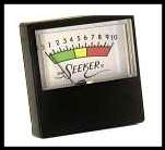 |
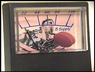
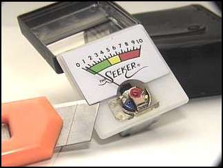
This is the meter as purchased. If you are
interested, these were purchased from All Electronics
(Standard, "Not affiliated" disclaimers) for
10@ $1.25 each, which I thought to be very reasonable for
a meter of this quality. It measures approximately
1.25" x 1.25". It is a 250ua movement. |
The first thing you must do is decide what you
want your meter to do. In this case, the purpose was to use them
as simple volt meter, which requires nothing more than inserting
an appropriate resistor in series with the meter. It is necesary
to mark or take notes as to where the applied measured voltage
reads on your un-modified meter dial, For example; with a 660K
resistor in series with the meter leads, the meter will read 135
volts full scale. If you will be using the meter for current
measurements, you will need to insert a meter shunt of a low
resistance value. Click here for more
information on creating a meter shunt. Otherwise, Most Electronic
Handbooks will give you specific details in making these shunts.
 |
The first mechanical step is to remove the meter
housing. Most meters are held together with nothing more
than scotch tape making it a simple matter to cut through
the tape with a sharp razor knife. In all of these
procedures, work carefully and patiently as the meter
mechanisms are delicate and will not suffer through
abuse. Be aware that many times they can be stubborn and
will fly apart with the slightest provocation. I am quite
experienced with this phenomona! |
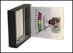 |
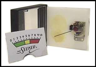
Open the meter carefully. I chose not to remove the
cover completely. This allows you to re-cover the meter
after removing the face plate, keeping dust and other air
borne particles from getting into the meter mechanism. |
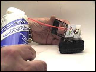
| The next step requires a gentle hand. You need to
remove the face plate from the meter housing.
Unfortunately, the plates are glued to the plastic
casing. If you attempt to pry the plate off, you will
either bend the plate, or damage the very delicate needle
mechanism of the meter. Freeze spray makes it into an
easy process. Using a very light spray, freeze the metal
plate causing the underlying glue to separate from the
plastic. On these meters, there is a very distinctive
cracking sound as the separation occurs. The meter plate
will very literally fall out of the housing. With
stubborn plates, a very light pry with your razor knife
will supply extra motivation for it to slide off. Be
carefull not to get any of the spray on your plastic
meter bezel, as the chemicals in the freeze spray will
cause a distortion in the plastic. |
 |
 |
 |
| The next step requires that you import the image of
the meter face to your graphics program. The easiest way
to do this is with a desk top scanner. Scanners have
become extraordinarily reasonably priced. The one I use
cost $39.95 after rebate. If you anticipate working on
many home brew projects, it is probably worthy of your
consideration. Otherwise you will need to measure the
plate as accurately as possible and electronically
re-create the face plate in your program. I have become
very accustomed to working in Paint Shop Pro, available
as a free 60 day trial on their web site. The screen
shots to follow are directly from this program. |
 |
 |
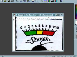
This is an actual screen shot of the scanned face
plate image. I try to scan at the maximum resolution that
I have the patience to use. Extremely high resolutions
take enormous processing times for each manipulation,
much like the TV commercial showing the process time of a
fast ball. I used 2400 dpi for these images. The higher
the resolution, the sharper the final printed image will
be, up to the limits of your printer. As you can see, the
scanner picks up (and adds) many imperfections to the
meter plate. Before working with the image, I usually
"clean" the image. |
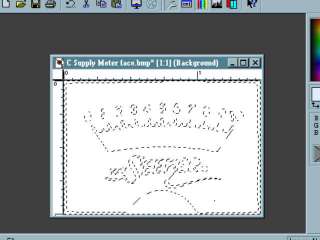
| The process starts by selecting all of the bright
areas of the image, using the "Magic Wand" in
Paint Shop Pro (PSP). This tool allows you to select
certain areas of the image for processing without
affecting the remainder of the image. Here, I have
selected the bright areas of the image and then used the
invert tool to select everything BUT the bright areas of
the image. Be sure to select the confined areas within
"Zero's" and "R's", etc. |
 |
 |
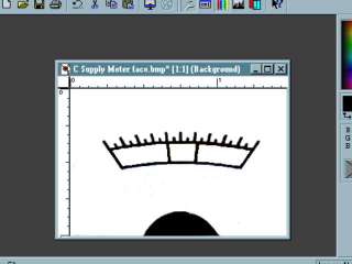
Once these areas are selected, simply "cut"
them from the image. In PSP, this automatically places
the cut image on the clipboard, which then allows it to
be used at a later time. Then De-select all areas of the
image, and clear the image which places a pure
white backgound on the workspace. In essence, you have
just created a pure white work space :-). The advantage
in going to this extra effort to create a white work
space is that you have the usable portion of your image
"Saved" on the clipboard, ready for
re-insertion. In addition, all of the original image
proportions are maintained. |
Here is a comparison of the original scanned image, to the
processed image on the right. Later, you will paint over the
extraneous lines on the top and sides with a white paint brush.
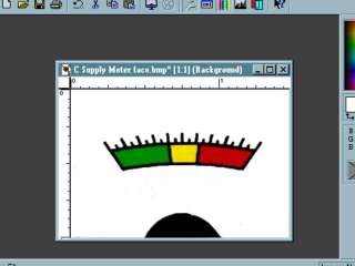
Next, eliminate all of the areas of the original meter that
you do not want. In PSP, using the "Magic Wand" again
makes the process easy. To eliminate the Red, Yellow and Blue,
use the "RGB" values option within the Magic Wand, and
then delete each color in turn. Use a white paint brush to paint
over the numbers that you do not need. From here, what you need
in a meter is of your own design and I can only offer the advice
of patience and experimentation to get exactly what you want in a
custom meter.
 |
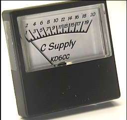
I chose a very simple design for these meters, so as
to compliment the rig for which they are intended. I used
a coarse brown spray tool to develop a texture to the
meter. The last step is to glue the printed face plate on
top of the original face plate, then trim to fit with a
razor knife.. |
 |
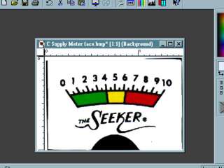
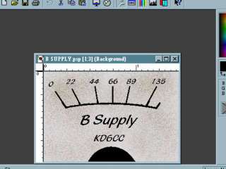
| Here is the final result. As you can see, I chose a
fairly plain and simple face for this project however,
there is nothing to limit your creativity! |
 |
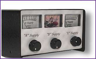
This a picture of the completed power supply.
The Suppy is intended to power Glowbug, or Tube Type Qrp Rigs.
For more pictures of this rig, Click Here.
Have Fun!
KD6CC
KR6LP - Lake Perris Qrp Society